Install components – Rockwell Automation 20B PowerFlex 700 Drive Components Replacement - Frame 8 User Manual
Page 32
32
Rockwell Automation Publication 20B-IN024C-EN-P - June 2012
Chapter 2
Basic Component Removal Procedures
Install Components
See the photographs in the preceding
section to
identify any components discussed in this section.
1. Replace the three positive (DC+) flexible capacitor busbars supplied in an
IGBT replacement kit on the back side of the transitional busbar for each
IGBT module being replaced.
2. Mount transitional busbar to bus capacitors. If needed, use a rubber mallet
to gently tap the transitional busbar onto the longer setscrews of the bus
capacitors.
3. Add a washer (rounded side down) and nut to each bus capacitor setscrew.
Finger tighten only.
4. Install the nine negative flexible capacitor busbars to the transitional
busbar with two washers (rounded side down) and two nuts for each
flexible capacitor busbar. Finger tighten only.
5. Install the six setscrews to secure the flexible capacitor busbars to each
IGBT board. Finger tighten only.
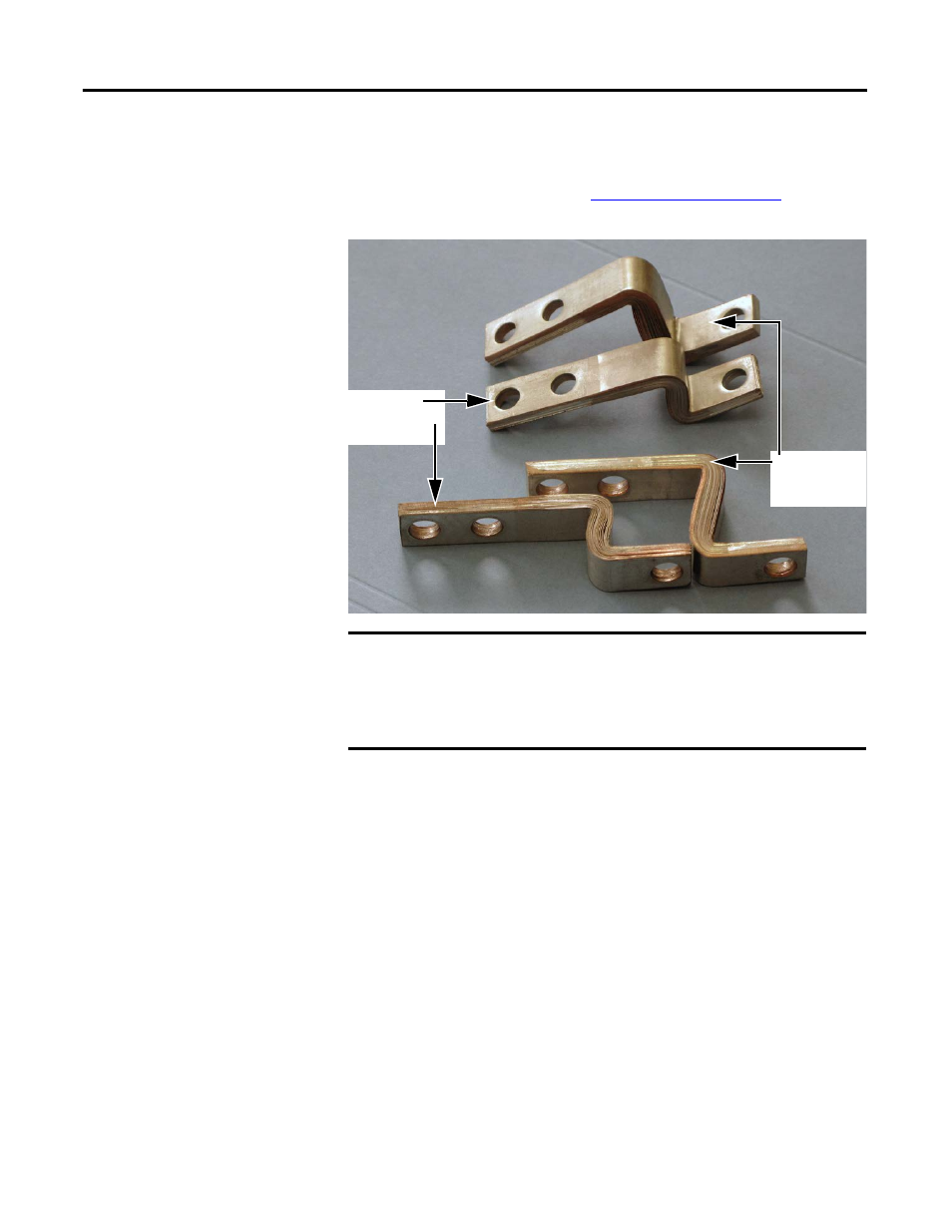
IMPORTANT
Each IGBT replacement kit includes three positive (DC+) and three
negative (DC-) flexible capacitor busbars. The positive ones are
shorter (see above) because they attach to the back side of the
transitional busbar. For ease of installation, replace positive flexible
capacitor busbars while the transitional busbar is removed.
Negative (DC-)
Flexible Capacitor
Busbar (tall)
Positive (DC+)
Flexible Capacitor
Busbar (short)