Rockwell Automation 22F PowerFlex 4M Quick Start FRN 2.xx User Manual
Page 2
Publication 22F-QS001D-MU-P – December 2008
Supersedes 22F-QS001C-MU-P - April 2008
Copyright © 2008 Rockwell Automation, Inc. All rights reserved.
UL508C
CSA 22.2
No. 14
EMC Directive 89/336/EEC, LV Dir. 73/23/EEC
LV:
EN 50178
EMC: EN 61800-3
U.S. Allen-Bradley Drives Technical Support
Tel: (1) 262.512.8176, Fax: (1) 262.512.2222, Email: [email protected], Online: www.ab.com/support/abdrives
Next parameter
Next parameter
FAULT
PROGRAM
FAULT
PROGRAM
Edit next paramete
Edit next paramete
Press to move from
digit to digit.
➊
➋
➌
➐
➏
➍
➎
Display Group
(View Only)
Display Group
(View Only)
Basic Program
Group
Basic Program
Group
Terminal Block
Group
Terminal Block
Group
Communications
Group
Communications
Group
Advanced Program
Group
➈
➉
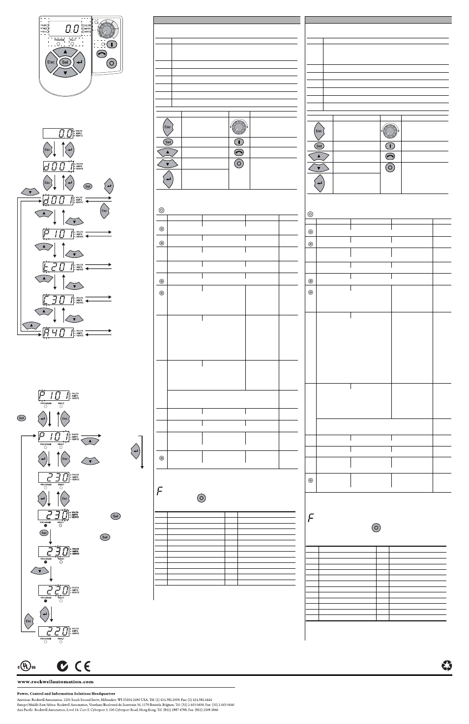
To Change a Parameter Value (Example)
パ ラ メ ー タ 値 を 変更す る に は ( 例 )
To Navigate Parameter Groups
パ ラ メ ー タ グ ル ー プ 間 を 移動す る に は
Display Group
(View Only)
Display グ ル ー プ
( 表示の み )
Basic Program
Group
Basic Program
グ ル ー プ
Terminal Block
Group
Terminal Block
グ ル ー プ
Communications
Group
Communications
グ ル ー プ
Advanced
Program Group
Advanced Program
グ ル ー プ
or
ま た は
Next parameter
次の パ ラ メ ー タ
or
ま た は
Edit next parameter
次の パ ラ メ ー タ の編集
Press
to move from
digit to digit.
[Sel] キ ー を 押 し て 、
桁 を 移動 し ま す。
or
ま た は
Quick Start (continued)
English
Integral Keypad
Basic Program Group Parameters
Fault Codes
is the fault designator.
To clear a fault, press Stop
, cycle power or set A450 [Fault Clear] to 1 or 2. For details on
fault codes, refer to the User Manual.
No.
LED
➊
Run/Direction Status (Red)
Note: Flashing means drive has been commanded to change direction. Indicates
actual motor direction while decelerating to zero.
➋
Alphanumeric Display (Red)
➌
Displayed Units (Red)
➍
Program Status (Red)
➎
Fault Status (Red)
➏
Speed Potentiometer Status (Green)
➐
Start Key Status (Green)
Key
Name
Key
Name
Escape
Speed Potentiometer
Select
Start
Up Arrow
Reverse
Down Arrow
Stop
Enter
= Stop drive before changing the value of this parameter.
No.
Parameter
Min/Max
Display/Options
Default
P101 [Motor NP Volts]
20/Drive Rated Volts
1 VAC
Based on
Drive
Rating
Set to the motor nameplate rated volts.
P102 [Motor NP Hertz]
10/400 Hz
1 Hz
60 Hz
Set to the motor nameplate rated frequency.
P103 [Motor OL Current]
0.0/(Drive Rated Amps
×
2) 0.1 Amps
Based on
Drive
Rating
Set to the maximum allowable motor current.
P104 [Minimum Freq]
0.0/400.0 Hz
0.1 Hz
0.0 Hz
Sets the lowest frequency the drive will output continuously.
P105 [Maximum Freq]
0/400 Hz
1 Hz
60 Hz
Sets the highest frequency the drive will output.
P106 [Start Source]
0/5
0 = “Keypad”
1
1 = “3-Wire”
2 = “2-Wire”
3 = “2-W Lvl Sens”
4 = “2-W Hi Speed”
5 = “Comm Port”
0
Sets the control scheme used to start the drive.
1
When active, the Reverse key is also active unless
disabled by A434 [Reverse Disable].
P107 [Stop Mode]
0/7
0 = “Ramp, CF”
1
1 = “Coast, CF”
1
2 = “DC Brake, CF”
1
3 = “DCBrkAuto,CF”
1
4 = “Ramp”
5 = “Coast”
6 = “DC Brake”
7 = “DC BrakeAuto”
0
Active stop mode for all stop sources [e.g. keypad,
run forward (I/O Terminal 02), run reverse (I/O
Terminal 03), RS485 port] except as noted below.
Important: I/O Terminal 01 is always a coast to
stop input except when P106 [Start Source] is set
for “3-Wire” control. When in three wire control, I/
O Terminal 01 is controlled by P107 [Stop Mode].
1
Stop input also clears active fault.
P108 [Speed Reference]
0/5
0 = “Drive Pot”
1 = “InternalFreq”
2 = “0-10V Input”
3 = “4-20mA Input”
4 = “Preset Freq”
5 = “Comm Port”
0
Sets the source of the speed reference to the drive.
Important: When t201 or t202 [Digital Inx Sel] is set to option 2, 4, 5, 6,
13 or 14, and the digital input is active, t201 or t202 will override the
speed reference commanded by this parameter. Refer to Chapter 1 of the
PowerFlex 4M User Manual for details.
P109 [Accel Time 1]
0.0/600.0 Secs
0.1 Secs
10.0 Secs
Sets the rate of acceleration for all speed increases.
P110 [Decel Time 1]
0.1/600.0 Secs
0.1 Secs
10.0 Secs
Sets the rate of deceleration for all speed decreases.
P111 [Motor OL Ret]
0/1
0 = “Disabled”
1 = “Enabled”
0
Enables/disables the Motor Overload Retention function.
P112 [Reset To Defalts]
0/1
0 = “Idle State”
1 = “Reset Defaults”
0
Resets all parameter values to factory defaults.
No.
Fault
No.
Fault
F2
Auxiliary Input
(1)
(1)
Auto-Reset/Run type fault. Configure with parameters A451 and A452.
F40
Phase W to Gnd
F3
Power Loss
F41
Phase UV Short
F4
UnderVoltage
(1)
F42
Phase UW Short
F5
OverVoltage
(1)
F43
Phase VW Short
F6
Motor Stalled
(1)
F48
Params Defaulted
F7
Motor Overload
(1)
F63
SW OverCurrent
(1)
F8
Heatsink OvrTmp
(1)
F64
Drive Overload
F12
HW OverCurrent
F70
Power Unit
F13
Ground Fault
F71
Net Loss
F33
Auto Rstrt Tries
F81
Comm Loss
F38
Phase U to Gnd
F100
Parameter Checksum
F39
Phase V to Gnd
F122
I/O Board Fail
『 ク イ ッ ク ス タ ー ト 』 ( 続 き )
日本語
内蔵キ ー パ ッ ド
Basic Program グ ル ー プ の パ ラ メ ー タ
フ ォ ル ト コ ー ド
デ フ ォ ル ト の指示子 で す か ?
フ ォ ル ト を ク リ ア す る に は、 [Stop]
キ ー を 押 し て 電源 を 切断後再投入す
る か ま た は A450 を 1 ま た は 2 に 設定 し ま す。 フ ォ ル ト コ ー ド の詳細は、
『 ユ ー ザ ー ズ マ ニ ュ ア ル』 を 参照 し て く だ さ い。
番号
LED
➊
実行 / 方向 ス テ ー タ ス ( 赤 )
注 : 点滅は、 ド ラ イ ブ が方向 を 変 え る よ う に 指示 さ れ て い る こ と を
示 し ま す。 ゼ ロ に 減速 し て い る 間 の、 実際の モ ー タ 方向 を 示 し ま
す。
➋
英数字表示 ( 赤 )
➌
表示 さ れ た 単位 ( 赤 )
➍
プ ロ グ ラ ム の ス テ ー タ ス ( 赤 )
➎
フ ォ ル ト の ス テ ー タ ス ( 赤 )
➏
速度ポ テ ン シ ョ メ ー タ の ス テ ー タ ス ( 緑 )
➐
[Start] キ ー の ス テ ー タ ス ( 緑 )
キ ー
名前
キ ー
名前
Esc
速度ポ テ ン シ ョ メ ー タ
選択
始動
上向 き 矢印
反転
下向 き 矢印
停止
Enter
= こ の パ ラ メ ー タ の値 を 変更す る 前 に 、 ド ラ イ ブ を 停止 し て く だ さ い。
番号
パ ラ メ ー タ
最小 / 最大
表示 / オ プ シ ョ ン
デ フ ォ ル ト
P101
[Motor NP Volts]
20/ ド ラ イ ブ 定格電圧
AC1V
ド ラ イ ブ
定格 に 基
づ く
モ ー タ 銘板の定格電圧 に 設定 し ま す。
P102
[Motor NP Hertz]
10/400 Hz
1 Hz
60 Hz
モ ー タ 銘板の定格周波数 に 設定 し ま す。
P103
[Motor OL Current]
0.0/( ド ラ イ ブ 定格電流 x
2)
0.1 A
ド ラ イ ブ
定格 に 基
づ く
許容可能な最大 モ ー タ 電流 に 設定 し ま す。
P104
[Minimum Freq]
0.0/400.0 Hz
0.1 Hz
0.0 Hz
ド ラ イ ブ が連続 し て 出力す る 最小周波数 を 設定 し ま す。
P105
[Maximum Freq]
0/400 Hz
1 Hz
60 Hz
ド ラ イ ブ が連続 し て 出力す る 最大周波数 を 設定 し ま す
P106
[Start Source]
0/5
0 =" キ ー パ ッ ド "
1
1 = " 線式 "
2 = "2 線式 "
3 = "2 線式レ ベ ル セ ン サ "
4 = "2 線式高速 "
5 = " 通信ポ ー ト "
0
ド ラ イ ブ の始動 に 使用 さ れ る 、 制御方式 を 設
定 し ま す。
(1)
ア ク テ ィ ブ に な っ て い る と き は、 A434 に
よ っ て 無効 に さ れ な い限 り 、 [Reverse] キ ー も
ア ク テ ィ ブ に な り ま す。
P107
[Stop Mode]
0/7
0 = " 減速停止 , CF"
1
1 = " コ ー ス ト ス ト ッ プ
( 惰走停止 )、 CF"
1
2 = "DC イ ン ジ ェ ク シ ョ
ン ブ レ ー キ停止 , CF"
1
3 = "DC イ ン ジ ェ ク シ ョ
ン ブ レ ー キ停止、 自動
シ ャ ッ ト オ フ 付 き 、 CF"
1
4 = " 減速停止 "
5 = " コ ー ス ト ス ト ッ プ
( 惰走停止 )"
6 = "DC イ ン ジ ェ ク シ ョ
ン ブ レ ー キ停止 "
7 = "DC イ ン ジ ェ ク シ ョ
ン ブ レ ー キ停止、 自動
シ ャ ッ ト オ フ 付 き "
0
す べ て の停止 モ ー ド に 対す る ア ク テ ィ ブ な停
止 モ ー ド [ 例、 キ ー パ ッ ド 、 正方向運転 (I/O
端子 02)、 逆方向運転 (I/O 端子 03)、 RS485
ポ ー ト ]、 し か し 、 下記の場合 を 除 く 。
重要 : P106 が 「3 線」 制御用 に 設定 さ れ て い
る と き を 除 き 、 I/O 端子 01 は入力 を 停止す る
ま で常 に 慣行運転 し ま す。 3 線制御 に な っ て い
る と き 、 I/O 端子 01 は P107 に よ っ て 制御 さ れ
ま す。
(1)
入力 を 停止す る と ア ク テ ィ ブ な フ ォ ル ト も
ク リ ア さ れ ま す。
P108
[Speed Reference]
0/5
0 = ド ラ イ ブ ポ テ ン シ ョ
メ ー タ
1 = " 内部周波数 "
2 = "0 ~ 10V 入力 "
3 = "4 ~ 20mA 入力 "
4 = " プ リ セ ッ ト 周波数 "
5 = " 通信ポ ー ト "
0
ド ラ イ ブ へ の速度 リ フ ァ レ ン ス の ソ ー ス を 設
定 し ま す。
重要 : i201 ま た は t202 が オ プ シ ョ ン 2, 4, 5, 6, 13, ま た は 14 に設定さ れ、 デ
ジ タ ル入力が ア ク テ ィ ブ で あ る場合、 t201 ま た は t202 は、 こ の パ ラ メ ー タ
に よ っ て指定さ れ た速度 リ フ ァ レ ン ス を無効に し ま す。 詳細は、 『PowerFlex
4M User Manual』 の第 1 章を参照し て く だ さ い。
P109
[Accel Time 1]
0.0/600.0sec
0.1sec
10.0sec
す べ て の速度増加 に 対 し て 加速度 を 設定 し ま す。
P110
[Decel Time 1]
0.1/600.0sec
0.1sec
10.0sec
す べ て の速度減少 に 対 し て 減速度 を 設定 し ま す。
P111
[Motor OL Ret]
0/1
0 = " 無効 "
1 = " 有効 "
0
モ ー タ ー過負荷保持機能の有効 / 無効。
P112
[Reset To Defalts]
0/1
0 = " ア イ ド ル状態 "
1 = " デ フ ォ ル ト 値へ の リ
セ ッ ト "
0
す べ て パ ラ メ ー タ の値 を 既定値 に リ セ ッ ト 。
番号
フ ォ ル ト
番号
フ ォ ル ト
F2
補助入力
(1)
(1)
自動 リ セ ッ ト / 実行 タ イ プ フ ォ ル ト パ ラ メ ー タ A451 と A452 で設定 し ま
す。
F40
位相 W を グ ラ ウ ン ト へ
F3
電源損失
F41
位相 UV 配線短絡
F4
不足電圧
(1)
F42
位相 UW 配線短絡
F5
過電圧
(1)
F43
位相 VW 配線短絡
F6
モ ー タ ス ト ー ル
(1)
F48
デ フ ォ ル ト の パ ラ メ ー タ
F7
モ ー タ 過負荷
(1)
F63
" ソ フ ト ウ ェ ア 過電流
(1)
F8
ヒ ー ト シ ン ク 温度超過熱
(1)
F64
ド ラ イ ブ 過負荷
F12
ハ ー ド ウ ェ ア 過電流
F70
ド ラ イ ブ 電源部
F13
地路
F71
ネ ッ ト ワ ー ク 損失
F33
自動実行再開試行
F81
通信損失
F38
位相 U を グ ラ ウ ン ト へ
F100
パ ラ メ ー タ チ ェ ッ ク サ ム
F39
位相 V を グ ラ ウ ン ト へ
F122
I/O ボ ー ド の故障