Powerflex 700 power jumpers 9 – Rockwell Automation 20B PowerFlex 700 Power Jumpers User Manual
Page 9
PowerFlex 700 Power Jumpers
9
Publication 20B-IN021B-EN-P
Frame
Vo
lt
ag
e
Code
Cur
rent
Rating
Factory Default Jumper Settings
Power Source Type
MOV/Input Filter
Caps
(1) (2)
DC Bus Common
Mode Caps
6
E
F
T
W
All
Two green/yellow
wires connected
to Power Terminal
Block “PE” and
chassis
Green/yellow wire
to CM Cap Board
is connected to
Power Terminal
Block “PE”
Solid Ground
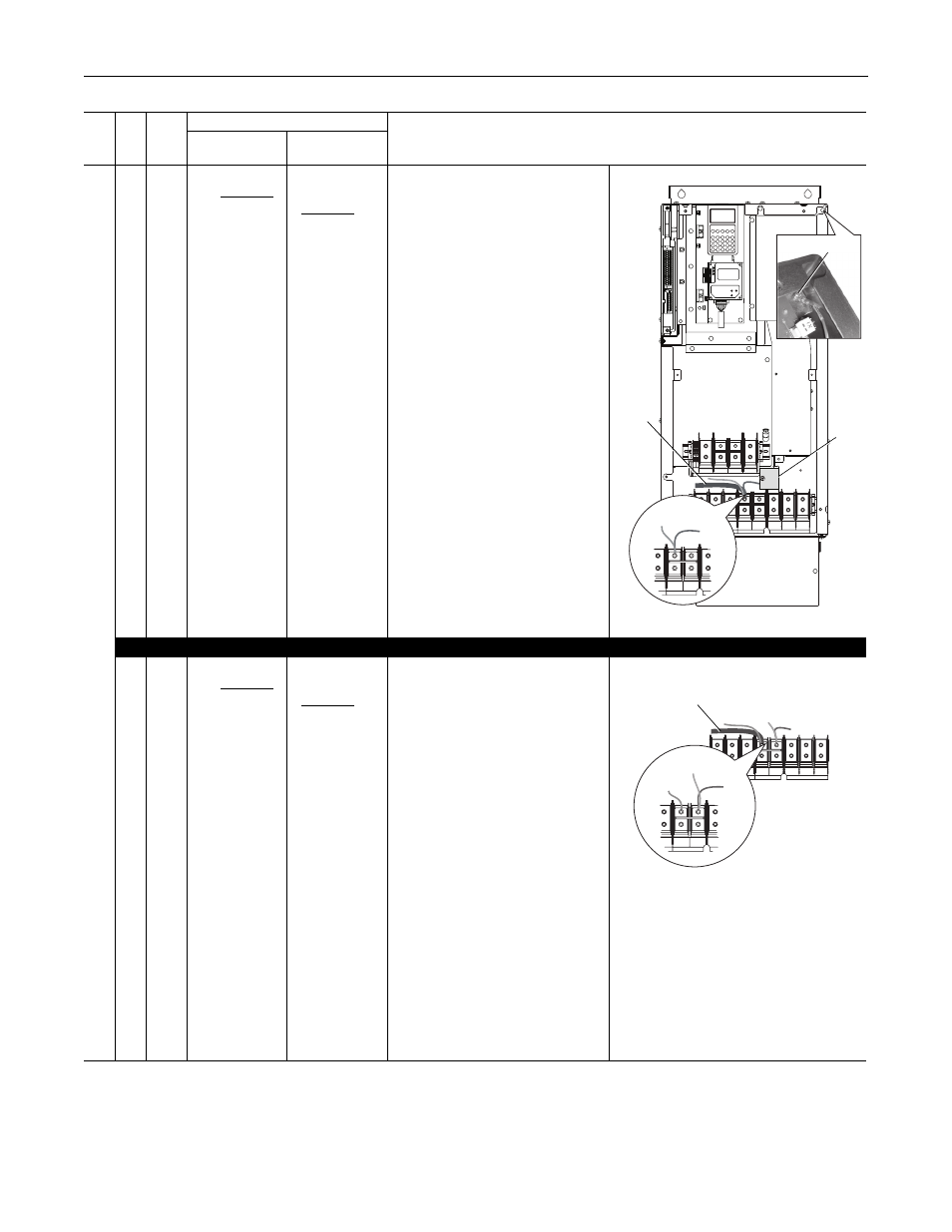
1. The green/yellow CM Cap and MOV
jumper wires should be connected to
“PE.”
2. The Input Filter Cap jumper wire (top
right) should be connected to chassis
ground with a metal screw. Verify. If
necessary, remove the nylon screw/
spacer and insert a metal M5 x 10
screw. Torque to 3.2 N•m (28 lb•in).
Non-Solid Ground
1. The green/yellow CM Cap and MOV
jumper wires should be insulated from
ground. If necessary, remove them
from “PE” and individually insulate/
secure each jumper wire to guard
against unintentional contact with
chassis or components. Important: Do
Not Remove/Disconnect the larger
green/yellow wire.
2. The Input Filter Cap jumper wire (top
right) should be insulated from ground
with a nylon screw/spacer. Verify. If
necessary, remove the metal screw
and insert a M5 x 15 nylon screw/
spacer.
NEMA/UL Type 12 Drives
C
D
E
F
P
R
T
W
All
Two green/yellow
wires connected
to Power Terminal
Block “PE”
Green/yellow wire
to CM Cap Board
is connected to
Power Terminal
Block “PE”
Solid Ground
1. The green/yellow CM Cap jumper wire
should be connected to “PE.”
2. The MOV/Input Filter Cap jumper wires
should be connected to “PE.”
Non-Solid Ground
1. The green/yellow CM Cap jumper wire
should be insulated from ground. If
necessary, remove the jumper wire
from “PE” and insulate/secure it to
guard against unintentional contact
with chassis or components.
Important: Do Not Remove/
Disconnect the larger green/yellow
wire.
2. MOV/Input Filter Cap jumper wires
should be insulated from ground. If
necessary, remove the jumper wires
from “PE” and individually insulate/
secure them to guard against
unintentional contact with chassis or
components.
(1)
AC input drives only. MOV’s and input filter caps do not exist on DC input drives.
(2)
When removing MOV’s, the input filter capacitor must also be removed.
DC–
DC+
BR1
BR2
USE 75 C COPPER WIRE ONLY, TORQUE 52 IN-LB (6 N-M)
22-10
AWG
5.3 IN-LB
(0.6 N-M)
WIRE STRIP
PS+
PS–
USE 75 C
COPPER WIRE
ONLY
TORQUE
52 IN-LB
(6 N-M)
U
T1
V
T2
W
T3
R
L1
S
L2
INPUT
OUTPUT
T
L3
PE
PE
Optional
Communications
Module
Input Filter Cap
PE
PE
MOV
CM Cap
DO NOT
REMOVE
MOV
U
T1
V
T2
W
T3
R
L1
S
L2
INPUT
OUTPUT
T
L3
PE
PE
PE
PE
MOV
Input Filter Cap
CM Cap
DO NOT
REMOVE