Rockwell Automation 20B PowerFlex 700 Power Jumpers User Manual
Page 6
Publication 20B-IN021B-EN-P
6
PowerFlex 700 Power Jumpers
Fra
m
e
Vo
lt
ag
e
Code
C
u
rrent
Ra
ti
ng
Factory Default Jumper Settings
Power Source Type
MOV/Input Filter
Caps
(1) (2)
DC Bus Common
Mode Caps
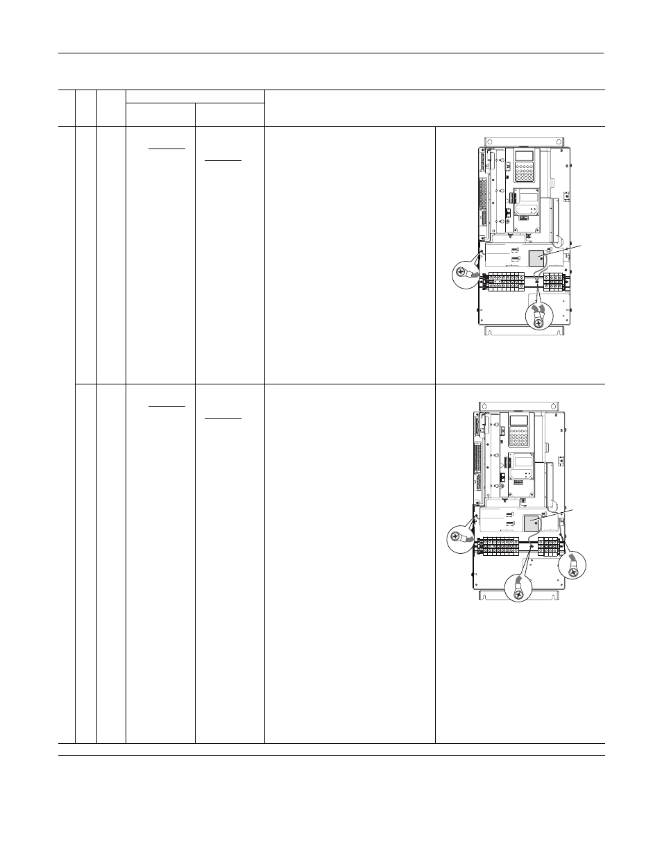
5
C
F
W
140
052
060
Two green/yellow
wires connected
to the Power
Terminal Block rail
Green/yellow wire
to CM Cap Board
is connected to
ground
Solid Ground
1. CM Cap jumper wire should be connected
to ground with a metal screw. Verify. If
necessary, remove the nylon screw/spacer
and insert a metal M5 x 8 screw. Torque to
3.2 N•m (28 lb•in).
2. MOV/Input Filter Cap jumper wires should
be connected to ground with a metal screw.
Verify. If necessary, remove the nylon screw/
spacer and insert a metal M5 x 12 screw.
Non-Solid Ground
1. CM Cap jumper wire should be insulated
from ground with a nylon screw/spacer.
Verify. If necessary, remove the metal screw
and insert a M5 x 15 nylon screw/spacer.
2. MOV/Input Filter Cap jumper wires should
be insulated from ground with a nylon
screw/spacer. Verify. If necessary, remove
the metal screw and insert a
M5 x 20 nylon screw/spacer.
E
F
T
W
077
082
099
098
Two green/yellow
wires connected
to chassis ground
Green/yellow wire
to CM Cap Board
is connected to
ground
Solid Ground
1. CM Cap jumper wire should be connected
to ground with a metal screw. Verify. If
necessary, remove the nylon screw/spacer
and insert a metal M5 x 8 screw. Torque to
3.2 N•m (28 lb•in).
2. MOV jumper wire should be connected to
ground with metal screws. Verify. If
necessary, remove the nylon screw/spacers
and insert a metal M5 x 12 screws.
3. Input Filter Cap jumper wire should be
connected to ground with a metal screw.
Verify. If necessary, remove the nylon screw/
spacer and insert metal M5 x 8 screw.
Non-Solid Ground
1. CM Cap jumper wire should be insulated
from ground with a nylon screw/spacer.
Verify. If necessary, remove the metal screw
and insert a M5 x 15 nylon screw/spacer.
2. MOV jumper wire should be insulated from
ground with a nylon screw/spacer. Verify. If
necessary, remove the metal screws and
insert a M5 x 20 nylon screw/spacer.
3. Input Filter Cap jumper wire should be
insulated from ground with a nylon screw/
spacer. Verify. If necessary, remove the
metal screws and insert a M5 x 15 nylon
screw/spacer.
Frame 5 continued on next page
(1)
AC input drives only. MOV’s and input filter caps do not exist on DC input drives.
(2)
When removing MOV’s, the input filter capacitor must also be removed.
WIRE RANGE: 14-1/0 AWG (2.5-35 MM2)
TORQUE: 32 IN-LB (3.6 N-M)
STRIP LENGTH: 0.67 IN (17 MM)
USE 75 C CU WIRE ONLY
POWER TERMINAL RATINGS
WIRE RANGE: 6-1/0 AWG (16-35 MM2)
TORQUE: 44 IN-LB (5 N-M)
STRIP LENGTH: 0.83 IN (21 MM)
GROUND TERMINAL RATINGS (PE)
300 VDC EXT PWR SPLY TERM (PS+, PS-)
WIRE RANGE: 22-10 AWG (0.5-4 MM2)
TORQUE: 5.3 IN-LB (0.6 N-M)
STRIP LENGTH: 0.35 IN (9 MM)
17
21
INPUT AC
OUTPUT
Optional
Communications
Module
9
CM Cap
MOV
MOV / Input Filter Cap
WIRE RANGE: 14-1/0 AWG (2.5-35 MM2)
TORQUE: 32 IN-LB (3.6 N-M)
STRIP LENGTH: 0.67 IN (17 MM)
USE 75 C CU WIRE ONLY
POWER TERMINAL RATINGS
WIRE RANGE: 6-1/0 AWG (16-35 MM2)
TORQUE: 44 IN-LB (5 N-M)
STRIP LENGTH: 0.83 IN (21 MM)
GROUND TERMINAL RATINGS (PE)
300 VDC EXT PWR SPLY TERM (PS+, PS-)
WIRE RANGE: 22-10 AWG (0.5-4 MM2)
TORQUE: 5.3 IN-LB (0.6 N-M)
STRIP LENGTH: 0.35 IN (9 MM)
17
21
INPUT AC
OUTPUT
Optional
Communications
Module
9
PE
CM Cap
MOV
MOV
Input Filter
Cap