Jumper settings and locations, 4powerflex 700 power jumpers, Cm cap mov – Rockwell Automation 20B PowerFlex 700 Power Jumpers User Manual
Page 4: Cm cap
Publication 20B-IN021B-EN-P
4
PowerFlex 700 Power Jumpers
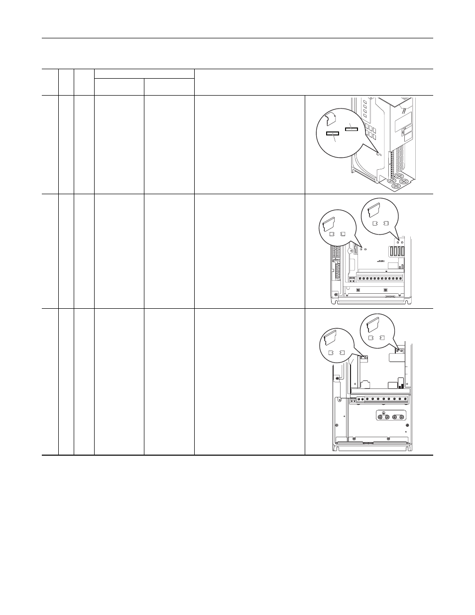
Jumper Settings and Locations
Fra
m
e
Vo
lt
ag
e
Code
C
u
rrent
Ra
ti
ng
Factory Default Jumper Settings
Power Source Type
MOV/Input Filter
Caps
DC Bus Common
Mode Caps
0…1
B
C
D
E
All
PE_B
Installed
PE_A
Installed
Solid Ground
• Remove the I/O Cassette (refer to the
User Manual for details). Verify that
jumpers are installed at the “PE_A” and
“PE_B” locations on the Power Board.
Non-Solid Ground
• Remove the I/O Cassette (refer to the
User Manual for details). Remove
jumpers at the “PE_A” and “PE_B”
locations on the Power Board.
2
B
C
D
E
All
PE_MOV
Installed
PE_CAP
Installed
Solid Ground
• Verify that jumpers are installed at the
“PE_CAP” and “PE_MOV” locations.
Non-Solid Ground
• Remove jumpers at the “PE_CAP” and
“PE_MOV” locations.
3…4
B
C
D
E
All
PE_MOV
Installed
PE-CAP
Installed
Solid Ground
• Verify that jumpers are installed at the
“PE_CAP” and “PE_MOV” locations.
Non-Solid Ground
• Remove jumpers at the “PE_CAP” and
“PE_MOV” locations.
BR1
BR2
DC+
DC–
PE
U/T1
V/T2
W/T3
R/L1
S/L2
T/L3
Use 75C
Wire Only
#10-#14 A
WG
Torque to 7 in-l
bs
!
DA
NGER
PE A
PE B
CM Cap
MOV
BR1 BR2 DC+ DC- U/T1 V/T2 W/T3
SHLD
SHLD
PE R/L1 S/L2 T/L3
PE 2
MOV-PE JMPR
PE 1
AUX IN+ AUX OUT–
75C Cu Wire
6 AWG [10MM
2
] Max.
12 IN. LBS.
1.4 N-M
} TORQUE
WIRE
STRIP
CONTR
O
L
PO
WER
PE 4
PE 3
MOV
PE_MOV
CM Cap
PE_CAP
BR1 BR2 DC+ DC- U/T1 V/T2 W/T3 R/L1 S/L2 T/L3
PE MOV
PE CAP
75C Cu Wire
3 AWG [25MM
2
] Max.
16 IN. LBS.
1.8 N-M
} TORQUE
WIRE
STRIP
CONTR
O
L
PO
WER
AUX IN
+ –
SHLD
SHLD
PE
75C Cu Wire
6 AWG [10MM2] Max.
BR1 BR2
12 IN. LBS.
1.4 N-M
} TORQUE
PE_CAP
PE_MOV
CM Cap
MOV