42crc mounting, Installation, Alignment – Rockwell Automation 42CRC Color Registration Control User Manual
Page 5
3
42CRC Color Registration Control
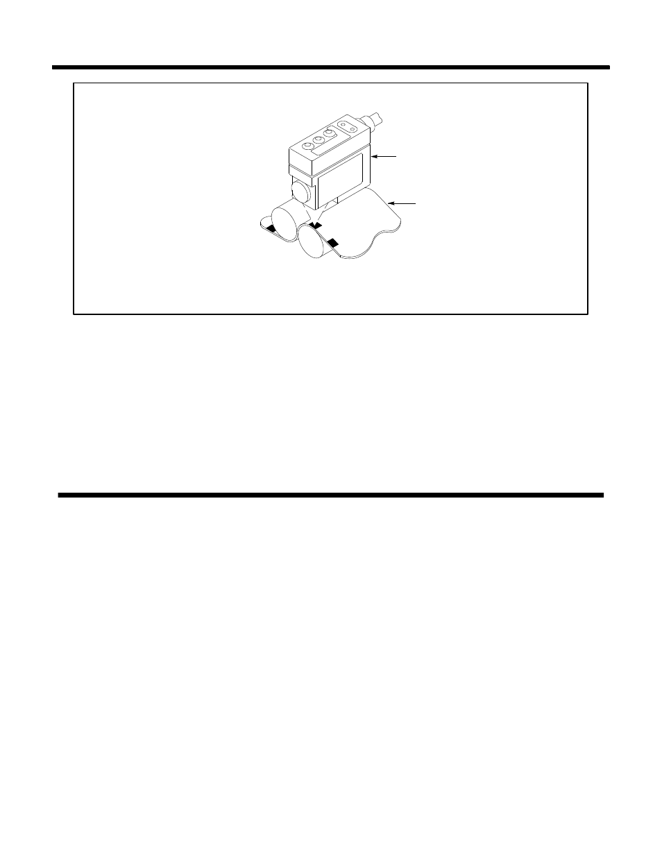
FIGURE 1
42CRC
WEB MATERIAL
MOUNT THE 42CRC OVER A PLATE OR ROLL TO
PREVENT FALSE SIGNALS DUE TO WEB FLUTTER
42CRC Mounting
c. Wiring
For proper wiring the 42CRC requires a Photoswitch Cable Assembly
#60-2292 ordered separately. The control operates on 10-30 VDC @ 70
mA max. See pages 11 and 12 for complete specifications. All external
wiring should conform to the National Electric Codes and applicable
local Codes. See wiring diagrams beginning on page 15 for external
connections.
The 42CRC is designed to perform reliably on many different types of web
material. However, once the device is mounted and wired, it should be
aligned to the particular web material for optimum performance and
reliability.
Most marks can be detected by using the following mounting and align-
ment methods. Difficult mark colors and some foil material may require
the use of the Test Points on the control to determine the best position for
maximum mark to background contrast (see Page 9, d., Contrast Check).
a. Opaque Reflective Web Material
For sensing light or dark registration marks on opaque reflective surfaces,
mount the control .5 (13 mm) above the surface of the material. If the sur-
face is shiny or reflective, angle the control about 10 to 15 degrees to the
perpendicular (75 to 80 from the control to the web surface). See Figure
2, Page 4.
b. Opaque Non-Reflective Web Material
For sensing light or dark registration marks on material with non-reflective
surfaces, mount the control .5 (13 mm) from the surface and perpendicu-
lar (90) to the web. See Figure 3, Page 4.
Installation
(Continued)
Alignment