Additional features, Function selector switch operating modes, Figure 7 – Rockwell Automation 42CRC Color Registration Control User Manual
Page 10
8
42CRC Color Registration Control
To avoid detecting the unwanted marks, the control can be disabled
“gated” during the times the unwanted marks appear (see Figure 9). The
control can be “gated” by using electromechanical or solid state contacts
synchronized with the machine cycle.
c. Diagnostic Alarm Output
This feature provides for advanced remote (via CRT or control panel alarm
indication) warning of gradual loss of signal strength due to misalignment,
dust or drift in mark contrast prior to loss of a control output signal,
avoiding unexpected process disruption.
The diagnostic alarm is a normally closed NPN output. This output goes to
the open (indicating) state when the signal margin drops below 1.5.X for
seven consecutive marks (this is to avoid a false alarm) of any period or
duration. The diagnostic output also goes to the indicating state when the
cable is severed or disconnected or when the power supply to the
control fails.
The first occurrence of a signal margin 1.7X, indicative of correction of a
fault condition resets the diagnostic alarm. Since the diagnostic alarm
feature is not time-based, its operation is not affected by operations
employing indefinite pauses.
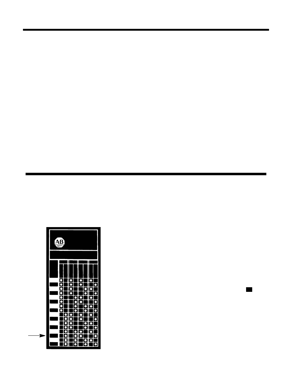
Two function switch selection charts are provided with
each registration control, one is attached to the control, the
other chart with adhesive backing can be mounted on the
machine for easy reference.
The selection chart makes it easy to select the proper op-
eration mode on the function switch shown in Figure 6.
Example: The operating mode required is as follows:
1. Output — Non-Latch
2. Spot (LED) Color-Green
3. Operating Mode — Automatic
4. Mark Color — Dark
Select a switch position which has a white dot in each of
the above columns.
The correct switch position for this application is
G
.
Additional Features
(Continued)
FIGURE 7
PHOTOSWITCH
COLOR
REGISTRATION
CONTROL
55-5080A
42CRC-4000
SW
ITCH
PO
SI
TI
ON
OUT
SPOT MODE
MARK
LA
T
C
H
NON
-LA
.
RED
G
R
EEN
AUT
O
MAN
U
AL
LI
GHT
DAR
K
A
A
B
B
C
C
D
D
E
E
F
F
G
G
H
H
Function Selector Switch
Operating Modes