Fig.4, Fig. 4 – Wolo 4200 The Commissioner User Manual
Page 4
ACCESSORY ROCKER SWITCHES:
LEFT ROCKER SWITCH IS CONTROLLED BY PINK WIRES
14. PINK FUSED WIRE: is connected to the vehicle’s fuse-block or a under dash power source that can supply 12-
volts / 15-amps. The pink wire is provided with an in-line fuse that must be used. The fuse should not be more then
ten-(10) inches from the power source. (Note: if you need to replace the fuse use a 15 amp type AGC).
15. PINK WIRE (WITHOUT FUSE): +12-volt power feed to warning light or accessory. IMPORTANT: do not exceed
15 amps.
RIGHT ROCKER SWITCH IS CONTROLLED BY YELLOW WIRES
16. YELLOW FUSED WIRE: is connected to the vehicle’s fuse-block or a under dash power source that can supply
12-volts / 15-amps. The yellow wire is provided with an in-line fuse that must be used. The fuse should not be
more then ten-(10) inches from the power source. (Note: if you need to replace the fuse use a 15 amp type AGC).
17. YELLOW WIRE: (WITHOUT FUSE): +12-volt power feed to warning light or accessory. IMPORTANT: do not
exceed 15 amps.
NOTE: It is important that any components connected to the yellow & pink wires, do not exceed the maximum
current rating, 15-amps.
NOTE: Tape all connections and secure wires.
18. Connect the male plug to its female mate in the rear of the siren controller. Note:
The plug is designed to connect and lock only in one position.
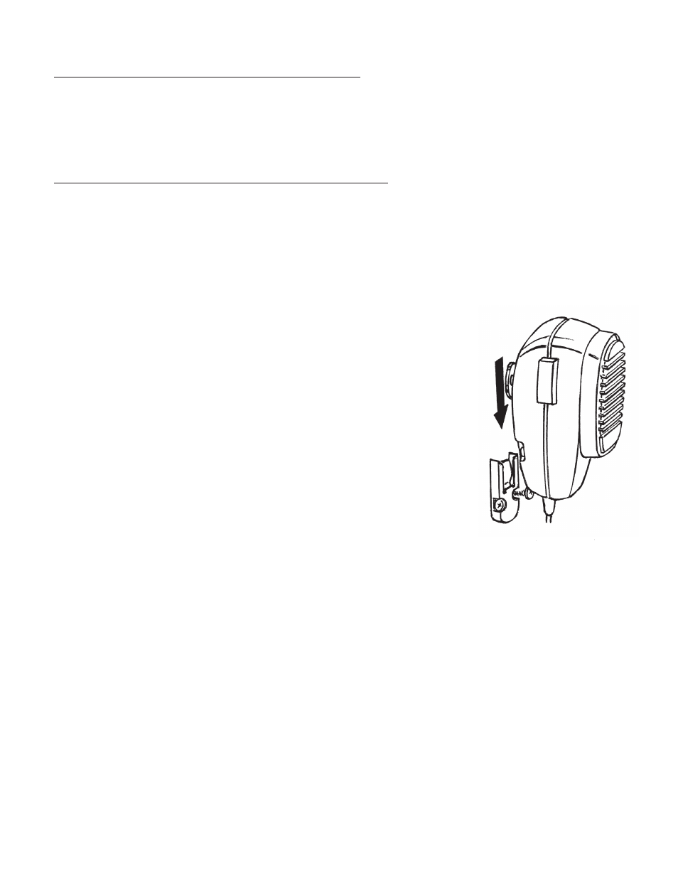
MOUNTING MICROPHONE HANGER BRACKET
Fig. 4
Select a location that the microphone can easily be reached. Using the microphone
hanger bracket as a template, mark the two locations and drill to size, 1/8” drill bit.
Secure the microphone bracket with the two-(2) sheet metal screws provided.
CAUTION: Before drilling the surface for mounting of the microphone bracket,
inspect the desired location to ensure that there are no components, wires and or
any other vehicle parts that could be damaged by drilling.
TESTING AFTER INSTALLATION
GAIN CONTROL: The GAIN CONTROL is used to turn on/off the siren controller
and adjust the volume. Turn the rotary GAIN control clockwise, which will turn on the siren controller. Further clockwise
rotation of GAIN control will increase the volume of all siren sounds, P.A system and radio rebroadcast. The maximum
clockwise position of the GAIN CONTROL is determined by either feedback or squeal being amplified. Adjust the GAIN
CONTROL to be positioned just before feedback occurs or to a sound level that is desired.
SELECTOR SWITCH: The rotary switch located in the center of the front panel is used to control five functions, which
are: three (3) different siren sounds, manual siren operation and radio rebroadcast.
19. Test each siren sound by positioning the selector control to the following positions:
14A.
• WAIL: When the selector is in this position the siren produces a “WAILING” sound that is continuous.
14A.
• YELP: When the selector is in this position the siren produces a “YELP” sound that is continuous.
14A.
• HI-LO: When the selector is in this position the siren produces a two-tone “HI-LO” sound that is continuous.
14A.
• MANUAL CONTROL SWITCH: The switch position allows the user to manually control two (2) siren sounds,
AIR HORN / SIREN. The manual control is located on the left side of the siren’s control panel. Lifting and
holding the red switch activates the air horn sound. Pressing down and holding the switch will active a powerful
siren. The manual switch will also override any siren that is in use.
14A.
• RADIO: If you have connected the two-way radio to the siren controller for radio rebroadcast (see step number
10), position the selector control to RADIO. Turn on the vehicle’s two-way radio. The radio’s rebroadcast volume
is controlled by the two way radio’s volume control.
P.A. SYSTEM:
20. Position the selector control to MANUAL. To test the P.A. system, depress the microphone’s push-to-talk button.
Speak into the microphone in a normal voice. The volume is controlled by the GAIN control. The P.A. system will
also override any siren that is sounding.
Fig. 4
ACCESSORY ROCKER SWITCHES:
LEFT ROCKER SWITCH IS CONTROLLED BY PINK WIRES
14. PINK FUSED WIRE: is connected to the vehicle’s fuse-block or a under dash power source that can supply 12-
volts / 15-amps. The pink wire is provided with an in-line fuse that must be used. The fuse should not be more then
ten-(10) inches from the power source. (Note: if you need to replace the fuse use a 15 amp type AGC).
15. PINK WIRE (WITHOUT FUSE): +12-volt power feed to warning light or accessory. IMPORTANT: do not exceed
15 amps.
RIGHT ROCKER SWITCH IS CONTROLLED BY YELLOW WIRES
16. YELLOW FUSED WIRE: is connected to the vehicle’s fuse-block or a under dash power source that can supply
12-volts / 15-amps. The yellow wire is provided with an in-line fuse that must be used. The fuse should not be
more then ten-(10) inches from the power source. (Note: if you need to replace the fuse use a 15 amp type AGC).
17. YELLOW WIRE: (WITHOUT FUSE): +12-volt power feed to warning light or accessory. IMPORTANT: do not
exceed 15 amps.
NOTE: It is important that any components connected to the yellow & pink wires, do not exceed the maximum
current rating, 15-amps.
NOTE: Tape all connections and secure wires.
18. Connect the male plug to its female mate in the rear of the siren controller. Note:
The plug is designed to connect and lock only in one position.
MOUNTING MICROPHONE HANGER BRACKET
Fig. 4
Select a location that the microphone can easily be reached. Using the microphone
hanger bracket as a template, mark the two locations and drill to size, 1/8” drill bit.
Secure the microphone bracket with the two-(2) sheet metal screws provided.
CAUTION: Before drilling the surface for mounting of the microphone bracket,
inspect the desired location to ensure that there are no components, wires and or
any other vehicle parts that could be damaged by drilling.
TESTING AFTER INSTALLATION
GAIN CONTROL: The GAIN CONTROL is used to turn on/off the siren controller
and adjust the volume. Turn the rotary GAIN control clockwise, which will turn on the siren controller. Further clockwise
rotation of GAIN control will increase the volume of all siren sounds, P.A system and radio rebroadcast. The maximum
clockwise position of the GAIN CONTROL is determined by either feedback or squeal being amplified. Adjust the GAIN
CONTROL to be positioned just before feedback occurs or to a sound level that is desired.
SELECTOR SWITCH: The rotary switch located in the center of the front panel is used to control five functions, which
are: three (3) different siren sounds, manual siren operation and radio rebroadcast.
19. Test each siren sound by positioning the selector control to the following positions:
14A.
• WAIL: When the selector is in this position the siren produces a “WAILING” sound that is continuous.
14A.
• YELP: When the selector is in this position the siren produces a “YELP” sound that is continuous.
14A.
• HI-LO: When the selector is in this position the siren produces a two-tone “HI-LO” sound that is continuous.
14A.
• MANUAL CONTROL SWITCH: The switch position allows the user to manually control two (2) siren sounds,
AIR HORN / SIREN. The manual control is located on the left side of the siren’s control panel. Lifting and
holding the red switch activates the air horn sound. Pressing down and holding the switch will active a powerful
siren. The manual switch will also override any siren that is in use.
14A.
• RADIO: If you have connected the two-way radio to the siren controller for radio rebroadcast (see step number
10), position the selector control to RADIO. Turn on the vehicle’s two-way radio. The radio’s rebroadcast volume
is controlled by the two way radio’s volume control.
P.A. SYSTEM:
20. Position the selector control to MANUAL. To test the P.A. system, depress the microphone’s push-to-talk button.
Speak into the microphone in a normal voice. The volume is controlled by the GAIN control. The P.A. system will
also override any siren that is sounding.
Fig. 4
Fig.4