Wolo 415-24 Airsplitter User Manual
Instal l ation instructions, Mode l s
INSTAL
L
ATION INSTRUCTIONS
for
Mode
l
s
400-24, 402
-
24, 403-24, 404-24, 405-24
,
415-24
&
41
7
-
24
The
c
R
l'b
rdonof a Wolo horn kit for your vehicle wil
l
provide an extra level of sound
.
The Wolo name
,
with more than
twenty
y
ears e
x
perience, is your guarantee of a superior horn product
.
If you need help
i
nstall
i
ng you
r
ne
w
Wolo horns
,
ou
r t
e
chni-
ci
ans are available to answer your questions, Monday through Friday from 9 AM to 4 PM EST
.
BBB
-
550-Horn (46
7
6)
.
1. I
ns
t
a
l
l the compressor
i
n
t
he eng
i
ne
c
ompar
t-
ment
i
n a dry location and safe from engine and
e
x
haust mani
f
old
hea
t
.
2
.
To secure the compressor
drill one 3/16
i
n
.
hole.
Mount the compresso
r
v
e
rtically
(air outlet on
t
op)
.
Install the head of the bolt into the slot on
t
he compressor
housing.
Secure the compres
-
so
r
to the vehicle using the lock washer/nut
pro-
v
ided
.
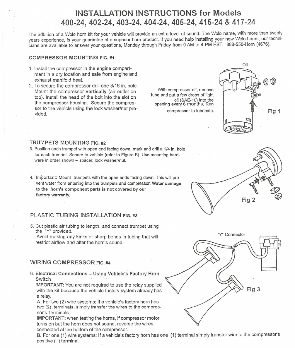
With comp
r
essor o
f
f
, r
emove
tube and pu
t
a
f
e
w
drops of l
i
ght
oil (SAE-10) into the
open
i
ng every 6 mon
t
hs
.
Run
compressor
t
o lubrica
t
e
.
TRUMPETS
MOUNTING
FIG. #2
3
.
Posi
ti
on each
t
rumpe
t w
ith open en
d
facing down
,
mark and dri
l
l
a
1/4 i
n
.
hole
f
or
e
ac
h t
rumpe
t
.
Secure
t
o vehicle (
r
efer
t
o F
i
gu
r
e
B)
.
Use moun
t
ing hard
-
wa
re in orde
r
sho
w
n
-
spacer
,
lock washer/nut
.
4. I
mpor
t
an
t: M
oun
t t
r
u
mpe
t
s
wit
h
t
he open ends
f
ac
i
ng do
w
n
.
Thi
s
will pre
-
vent w
ater f
r
om ente
r
ing in
t
o
t
h
e tr
umpets and comp
r
essor
; Wat
e
r d
a
m
a
ge
t
o
t
he
h
o
rn'
s
c
o
mponent
pa
r
t
s
i
s
n
o
t c
ov
er
e
d
by
our
f
ac
t
o
r
y wa
rran
ty
.
5
.
Cu
t
plastic ai
r t
ub
i
n
g t
o
l
e
n
gth
,
and connect tru
m
pe
t
us
i
ng
the
"
Y
"
provide
d
.
Avoi
d
mak
i
ng an
y
ki
n
ks o
r
sharp bends
i
n tubing
t
hat
w
ill
r
estr
i
ct a
i
rf
l
ow and al
t
er
t
he
h
orn'
s
sound.
6. Ele
c
tri
ca
l
Conn
e
cti
o
ns
- Using Vehicle's
Factory
H
orn
Swit
c
h
.
.
.
IMP
O
RTANT: Y
ou are no
t r
eqUired
t
o
u
se
t
he
r
elay s
u
pplied
w
i
t
h
t
he
ki
t because the vehicle fac
t
ory system a
l
ready has
a rela
y
.
A
.
For t
w
o (2) wire s
y
s
t
ems
:
I
f
a vehicle
'
s
f
acto
r
y ho
r
n has
t
w
o (
2
) term
i
nals
,
s
i
mply
t
ransfer t
h
e
w
ires
t
o the com
p
res
-
sor's terminals.
IM
POR
TANT:
when
t
est
i
ng
t
he ho
rn
s
,
i
f
co
m
pressor
moto
r
t
urns on but the horn does no
t
sound
, r
everse
t
he wires
connected
at the bo
t
tom o
f
the compressor.
B
.
For one (1) w
i
re systems
:
I
f
a vehicle
'
s fac
t
ory horn
:
has one (1) te
r
minal simply transfe
r
wire to
t
he compresso
r's
pos
i
tive
(+)
term
i
nal
.