End of life - not recommended for new designs, Figure 1. autoranging megapac architecture – Vicor Autoranging MegaPAC AC-DC Switcher User Manual
Page 4
UG:106
vicorpower.com
Applications Engineering: 800 927.9474
Page 4
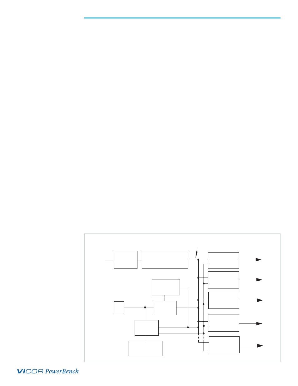
Voltage conversion in the output assemblies is achieved by Vicor's family of
Zero-Current-Switching (ZCS) DC-DC converters. These are forward converters in which
the main switching element switches at zero current. This patented topology has a
number of unique attributes: low switching losses; high frequency operation resulting
in reduced size for magnetics and capacitors; excellent line and load regulation; wide
adjustment range for output; low EMI/RFI emission and high efficiencies.
At initial power-up, the Autoranging MegaPAC outputs are disabled to limit the inrush
current, reduce peak currents in the autoranging relay contacts, and allow the DC bus
potential to settle out to the correct operating level. A low-power flyback converter
operating with PWM current-mode control converts the high voltage DC bus into
regulated low voltage to power the internal housekeeping circuits and DC cooling
fan. When operating on 115 Vac, the internal housekeeping Vcc comes up within 1s
after the application of input power. On 230 Vac, it comes up within 500 ms. The input
range selection circuit may take up to 200 ms to select the range if 115 Vac is applied.
When 230 Vac is applied, the circuit immediately selects for operation on 230 Vac.
Once the input range selection has taken place, the AC Power OK signal asserts to a
TTL "1" indicating that the input power is OK, and allows the power outputs to come up
typically within 15-30 ms later. An auxiliary Vcc output of 5 Vdc sourcing up to 0.3 A is
provided for peripheral use.
An output Enable/Disable function is provided by using an optocoupler to control
the Gate In pins of the ConverterPAC assemblies. If the Enable/Disable control pin is
pulled low, the optocoupler turns on, pulling the Gate In pin low and disabling the
ConverterPAC output. The typical delay associated for an output to come up when
measured from release of the Enable/Disable pin is 5-10 ms. The General Shutdown
function controls all outputs simultaneously and works in a similar manner.
The ride-through (holdup) time is the amount of time the load can be supported before
loss of output regulation after the loss of input power. Detecting the loss of input power
takes a finite time period, after which the AC Power OK signal goes from a TTL “1” to “0.”
This signal is available for use within 1.2 seconds after initial power-up and can be used
to indicate an impending loss of power. A minimum of 3 ms warning time is given.
Following the loss of input power, the outputs are disabled after the bus voltage drops
below its operating limit.
EN 55022
Level A
Power
Input
DC/DC Output
Assembly #1
DC/DC Output
Assembly #2
DC/DC Output
Assembly #3
Power Output
Power Output
Power Output
DC/DC Output
Assembly #8
Power Output
DC/DC Output
Assembly #4
Inrush Current &
Autoranging Control
Power Output
AC/DC Power Rectification,
Inrush Current Limiting,
Input Voltage Strapping
Logic Power
Supply
Housekeeping
Circuits
Customer Interface
(Optoisolators)
DC Bus Sense
Control
DC
Fan
High Voltage Unregulated
300 VDC Bus
Figure 1.
Autoranging MegaPAC
Architecture
End of Life - Not Recommended for New Designs