Electric heater, Preparation, Installation – Titus VAB IOM User Manual
Page 6: Startup, Operation and maintenance, Vab installation manual
VAB Installation Manual
IOM-VAB-00
06-30-04
6 of 7
Electric Heater
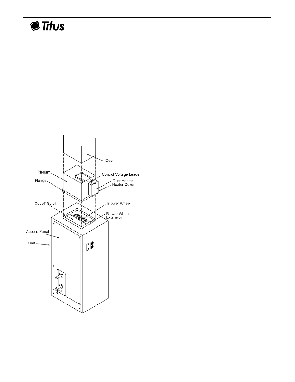
Figure 8 shows electric heater components and their
placement and orientation to a VAB unit.
Preparation
Some items to consider prior to installing electric heat are
as follows:
•
Duct materials must be suitable for 250º F operation.
See NFPA 90A and 90B pamphlet.
Note: Electric heaters are incompatible with discharge
equipment.
•
Ensure ample room exists in the ductwork. Electric
heat must have at least 24 inches of straight duct
clearance before an elbow. If 24 inches are
unavailable, devices such as turning vanes or baffles
may be required.
Figure 8. VAB Unit with Electric Heater
Components
Installation
Use the following information to install electric heat on
VAB models.
1.
Position heater element section over the blower
wheel of the VAB unit.
Note: Heater baffle must align with blower cut-
off scroll. If necessary, rotate heater 180
degrees to align. This ensures proper blower
discharge of air over the heater elements.
2.
Attach electric heat plenum to VAB unit using #6 or
larger sheet metal screws.
Note: Ensure plenum securely attaches to VAB
unit only and not just to blower wheel
extension.
3.
Add insulation, if necessary, to outside of heater
plenum section.
Warning: Do not insulate duct heater.
Startup
Check the following items before startup.
•
Ensure all shipping bolts and screws are removed;
plus, ensure all other bolts and screws are tight.
•
Verify the voltage and phase on the unit nameplate,
and ensure it is the same as the motor wired.
•
Check the alignment of the sheaves (pulley wheels)
and ensure the setscrews are tight.
•
Check for proper rotation of the blower pulley.
•
Check motor phase and rotation.
−
Exchanging two of the three leads at the unit
junction box can reverse three-phase motor
rotation.
−
Exchanging leads inside the motor junction box
can reverse the rotation of single-phase motors.
Refer to the motor nameplate.
−
Not all installations require a starter (some
motors utilize a contactor).
•
Ensure all filters are installed.
•
Make sure all doors and panels are in place.
•
Check the amperage draw of the motor. The
amperage draw should not exceed the nameplate
amps shown on the motor serial plate.