Ductwork, Duct insulation and vapor proofing, Motors and drives – Titus VAB IOM User Manual
Page 4: Sound attenuation, Electrical connections, Condensate drain, Installation, Vab installation manual
VAB Installation Manual
IOM-VAB-00
06-30-04
4 of 7
Installation
Basic installation procedure covers verifying and/or
installing the following items.
•
Ductwork
•
Duct insulation and vapor proofing
•
Motors and drives
•
Sound attenuation
•
Electrical connections
•
Condensate drain
•
Water piping
Ductwork
Use accepted industry practices and design guidelines of
the ASHRAE Fundamentals Handbook. Ductwork must
comply with all building codes and the National Fire
Protection Association’s pamphlet 90A and 90B.
Carefully inspect any previously installed ductwork to
determine suitability.
Note: Ductwork should be of a size meeting
requirements of the installation. Ductwork should
transition gradually from a smaller size blower outlet to
required duct run size to avoid excessive loss of air
velocity.
When return air duct connection is smaller than return air
inlet opening, construct the transition piece so the vertical
and horizontal dimensions of transition do not increase
more than one inch for every seven inches of length.
Allow a minimum of three feet of straight ductwork
following an equipment outlet.
Duct Insulation and Vapor Proofing
Previously installed heating supply ductwork may already
have adequate insulation against excessive heat loss.
This insulation may be satisfactory for protection against
heat gain from summer cooling. Depending upon
application, additional insulation may be required.
Externally insulated ductwork must have adequate vapor
seal for summer operation, especially where duct is
exposed to high humidity conditions.
Motors and Drives
Units are normally shipped with motor and drive installed.
However; when mounting a motor on the adjustable base
in the field, use extreme care to ensure proper alignment
and belt tension.
Sound Attenuation
Flexible duct connections should be used between the unit
and both the supply and return ducts.
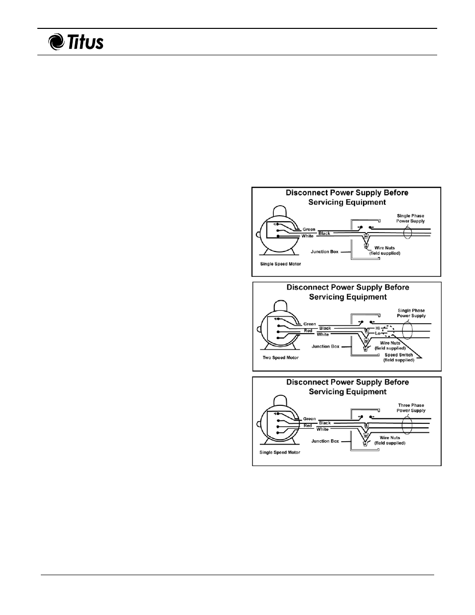
Electrical Connections
Each unit has a mounted control box, and typically, the
motor is to be wired to this box. Only ODP, single- and
three-phase motors on 800 to 2000 CFM units are factory-
wired to junction box. All other motors require field wiring
to junction box located on side of the unit cabinet.
Note 1: Unit must be permanently grounded in
accordance with NEC and local codes and ordinances.
See the typical wiring diagrams shown in Figure 5.
Note 2: Not all installations require a starter (some
motors utilize a contactor).
Figure 5. Wiring Diagrams