Control console acc1: small system, Installation & operation – Titus ACC1 Small System Console User Manual
Page 5
A D V A N C E D T E C H N I C A L M A N U A L
Control Console
ACC1: Small System
Installation & Operation
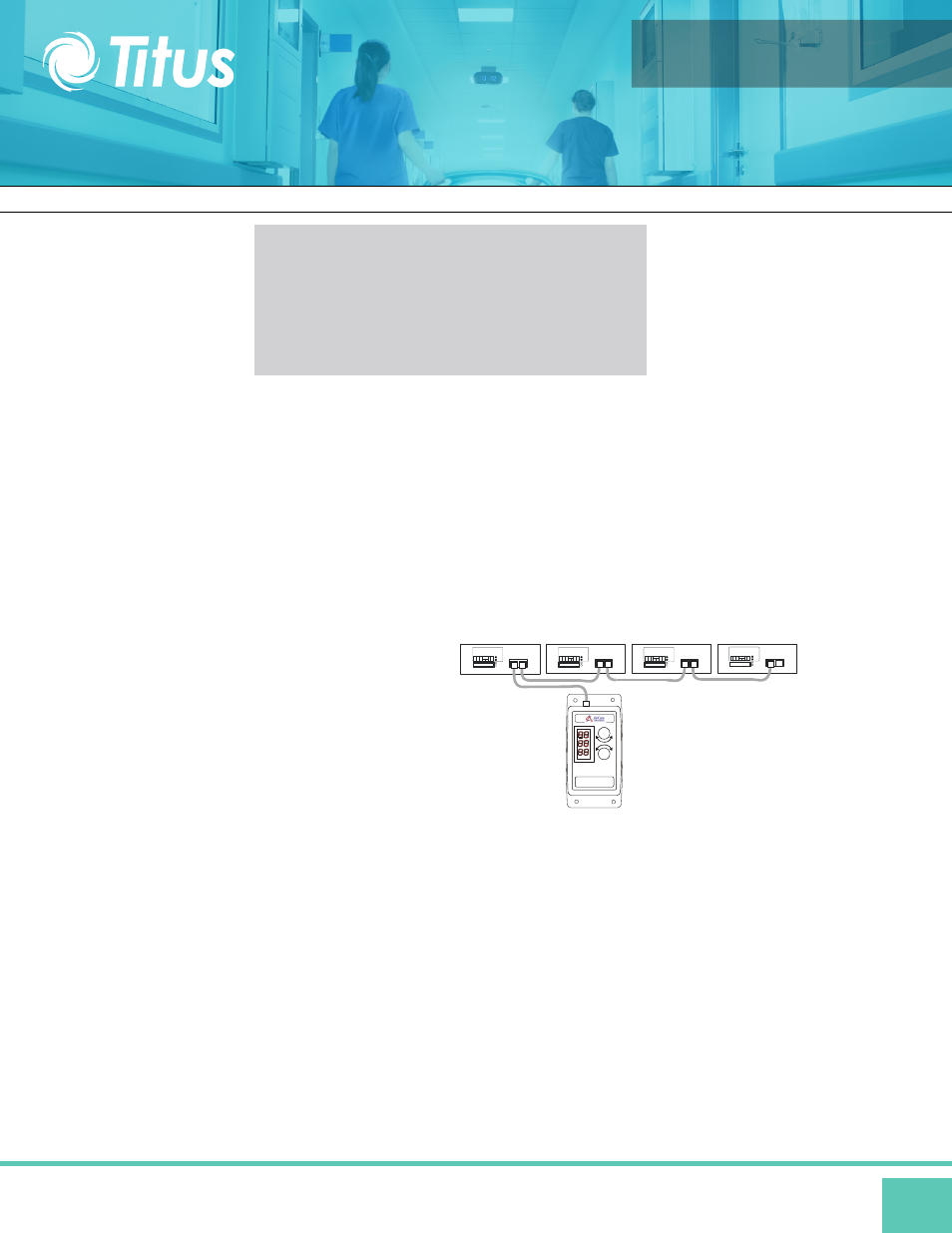
The control console can be wall mounted in the cleanroom or at a remote location; however, the maximum recommended distance from the
beginning to the end of the daisy chain should not exceed 800 linear feet.
Network Wiring
Cabling shall be provided and installed by others.
Plenum rated CAT5 cabling is recommended and network cable requirements should be specified based on the following:
A network is constructed by simply daisy-chaining Titus fan filter units via the universal
control card or network control card of each fan filter unit. Specific network wiring information
can be found in the istallation and operation manual for the speicfic unit type.
Network cable requirements should be based on:
• Distance Between Nodes
• Total Network Length
• Noisy Electrical Environment
• Environmental Conditions
• Mechanical Issues
5
The Titus Control Systems are
engineered for easy installation. However,
testing either before permanent installation or
as the system is installed is strongly
recommended.
INSTALLATION
Electrical Specifications
• Supply Voltage: 6-12 Vdc
• Typical Supply Current: 90 mA
• Network Transceivers: 2-wire, 1/8 Unit Load Type
• Operating Temperature: 0-40° Celsius (32-104°F) DC
• Power Connector: 2.1 mm DC Power Jack MODBUS
• Network: RJ45 Socket
Once the control console has been connected to at least one fan filter unit, power can be applied. The control console will automatically
scan the network.
Each fan filter unit should be given a unique address within the control console’s available address range (determined by model number.)
The addresses do not need to be contiguous, but contiguous addressing will make operator functions easier.
If power is turned off & on to any module or console in the network, its functionality and settings will be immediately restored to the same
state before power loss.
All unit control cards must be pre-set with a unique address within the range of the ACC1
DC power to the console can be provided via:
1) Power Supply module connected to the DC power jack,
2) Battery Pack (4 AA batteries), or
3) MODBUS network cable via ACM1008 module connected to the network.