Installation, Wall switch, Optional wall thermostat – Regency Horizon HZ33CE Small Gas Fireplace User Manual
Page 41: Optional remote control, Aeration adjustment, Battery installation
Regency HZ33CE Gas Fireplace
41
INSTALLATION
WALL SWITCH
1. Run the supplied wire through the right or
left side gas inlet opening. Be careful not
to damage wire.
Note: We recommend a maximum of 15'
of wire but if you wish to go with a
longer run, use the Thermostat Wire
Table.
2. Connect the wire to the wall switch and
install into the receptacle box. Also attach
wires to the valve as shown below.
Optional
WALL THERMOSTAT
A wall thermostat may be installed if desired,
connect the wires as per the wiring diagram.
Use table below to determine the maximum
wire length.
Note: Preferable if the thermostat is
installed on an interior wall.
Regency
®
offers an optional programmable
thermostat but any 250-750 millivolt rated non-
anticipator type thermostat that is CSA, ULC or
UL approved may be used.
CAUTION
Do not wire millivolt
wall thermostat wires
to 120V wire.
Thermostat Wire Table
Optional
REMOTE CONTROL
Use the Regency
®
Remote Control Kit approved
for this unit. Use of other systems may void
your warranty.
The remote control kit comes with a hand held
transmitter, a receiver and a wall mounting plate.
1. Choose a convenient location on the wall
to install the receiver and the receptacle
box (protection from extreme heat is very
important). Run wires from the fi replace to
that location. Use Thermostat Wire Table.
2. Connect the two wires to the gas valve. See
wiring diagram. Wall switch GT/GTM using
wire 0.584.907
CAUTION
Do not wire millivolt
remote control wires
to 120V wire.
3. Install 3 AAA alkaline batteries in transmitter
and 4 AA alkaline batteries in the receiver.
Install the receiver and its cover in the wall.
Switch the remote receiver to "remote"
mode. The remote control is now ready for
operation.
AERATION
ADJUSTMENT
The burner aeration is factory set but may need
adjusting due to either the local gas supply or
altitude. Open the air shutter for a blue fl ame by
pulling down on the rod or close for a more yellow
fl ame by pushing up on the rod.
Minimum Air Shutter Opening:
NG
1/16"
NG with Logs
3/16”
NG with Stones
3/16”
LP `
3/16"
LP with Logs
Full open
LP with Stones
Full open
CAUTION: Carbon will be produced if air shutter
is tightly closed.
Note: Any damage due to carboning
resulting from improperly setting
the aeration controls is NOT covered
under warranty.
Recommended Maximum Lead Length
(Two-Wire) When Using Wall
Thermostat (CP-2 System)
Wire Size
Max. Length
14 GA.
50 Ft.
16 GA.
32 Ft.
18 GA.
20 Ft.
20 GA.
12 Ft.
22 GA.
9 Ft.
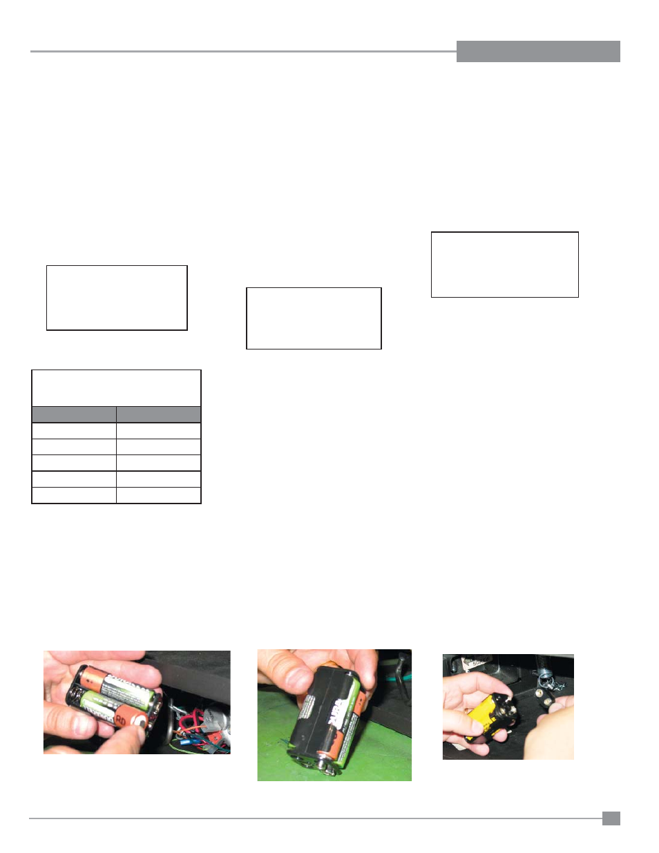
BATTERY INSTALLATION
1. 4 AA batteries must be installed in the battery pack to operate the burner switch.
2. Install 2 AA batteries per side and connect as shown below - the battery pack is located on the lower left side of the unit.
CAUTION
Do not wire millivolt
wall switch wire
to 120V wire.