Fairing surface cleanliness, Secure fts, Over horizon telemetry – Orbital Minotaur I User Manual
Page 78
Minotaur I User’s Guide
Section 8.0 – Optional Enhanced Capabilities
8.6.4. Fairing Surface Cleanliness
The inner surface of the fairing and exposed launch vehicle assemblies are cleaned to Visibly Clean Plus
Ultraviolet cleanliness criteria which ensures no particulate matter visible with normal vision when
inspected from 6 to 18 inches under 100 foot candle incident light, as well as when the surface is
illuminated by black light at 3200 to 3800 Angstroms. Process and procedures for inspection and the
bagging of material to preclude contamination during shipment to the field are in place.
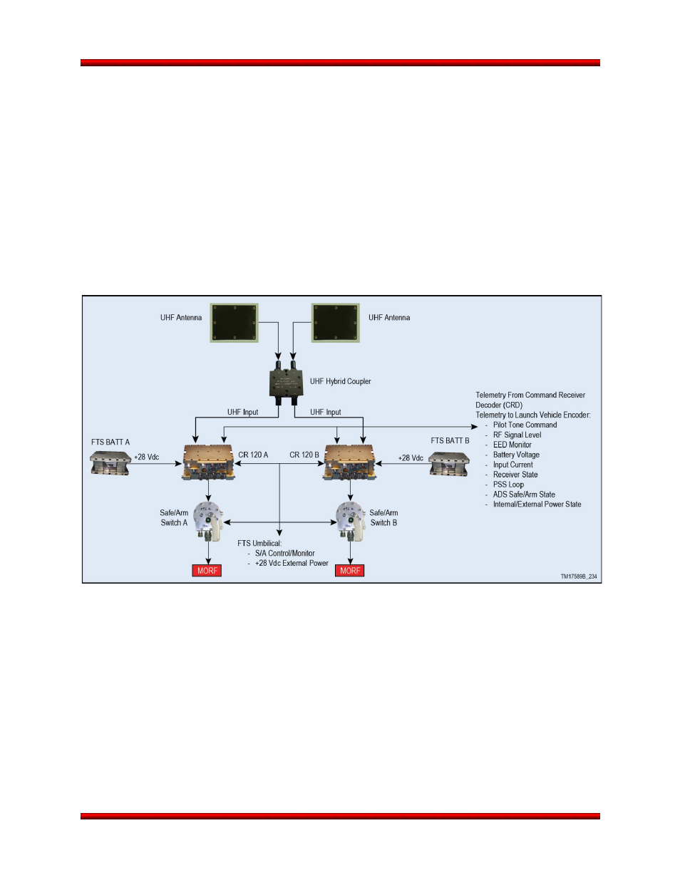
8.7. Secure FTS
The Secure FTS (Figure 8.7-1) is achieved with the L-3 Cincinnati Electronics Model CRD-120/205
Launch Vehicle Command Receiver/Decoder that is compatible with the "High-Alphabet" range safety
modulation format. The receiver uses a pre-stored code unique to each specific vehicle to issue
configuration and termination commands. This provides an increased level of security over the standard
FTS systems that use a basic 4 tone combination for receiver command and control.
Figure 8.7-1. Orbital’s Secure FTS System Block Diagram
The CRD-120/205 Launch Vehicle Command Receiver/Decoder was designed specifically to operate on
the Delta expendable space launch vehicles for range safety flight termination. This design incorporates
redundancy in both hardware and software and High Reliability piece-parts (in accordance with ELV-JC-
002D) to ensure reliable, fail-safe operation.
8.8. Over Horizon Telemetry
A Telemetry Data Relay Satellite System (TDRSS) interface can be added as an enhancement to provide
real-time telemetry coverage during blackout periods with ground based telemetry receiving sites. TDRSS
was successfully demonstrated on past Minotaur missions. The TDRSS telemetry system enhancement
consists of a LCT2 TDRSS transmitter, an antenna (Figure 8.8-1), an RF switch, and associated ground
test equipment. The RF switch is used during ground testing to allow for a test antenna to be used in lieu
of the flight antennas. Near the time when telemetry coverage is lost by ground based telemetry receiving
Release 3.0
March 2014
65