C. standard setpoint: 18.3 c (65 f), D. dew point temperature: 3 to 17 c (38 to 62 f), F. nominal flow: 11.3 m3/min (400 cfm) – Orbital Minotaur I User Manual
Page 38: Powered flight, Minotaur i user’s guide
Minotaur I User’s Guide
Section 4.0 – Payload Environment
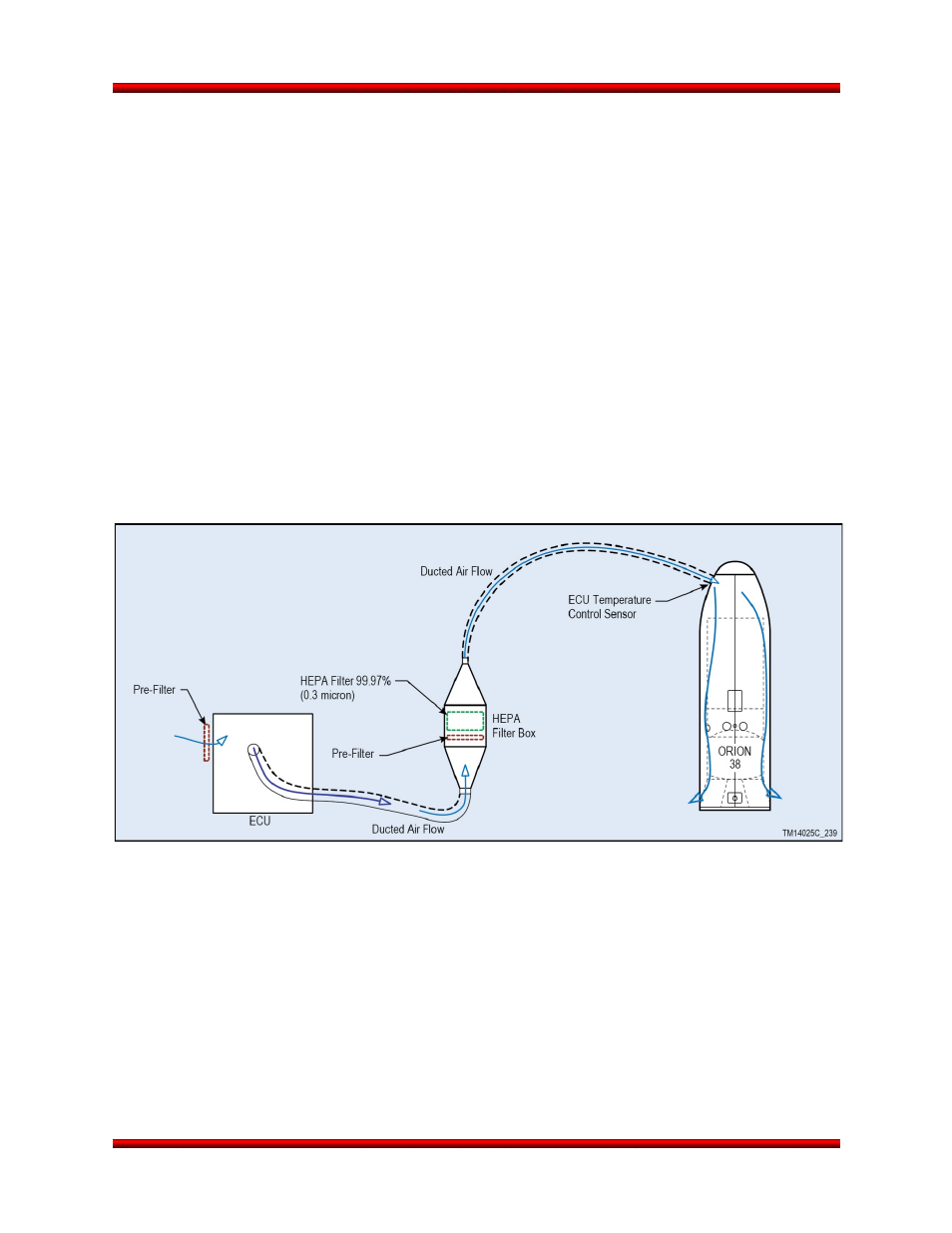
provides conditioned air to the payload in the Payload Processing Facility (PPF) after fairing integration
and on the launch pad. For Minotaur I, conditioned air is not provided during transport and lifting
operations. The conditioned air enters the fairing at a location forward of the payload, exits aft of the
payload and is maintained up to 5 minutes prior to launch (for the 61” fairing, the conditioned air can be
maintained until liftoff). A diffuser is designed into the air conditioning inlet to reduce impingement
velocities on the payload. Class 10,000 (ISO 7) can be provided inside a clean room and at payload
fairing HVAC inlet on a mission-specific basis as an enhanced option (Section 8.6).
Fairing inlet conditions are selected by the customer, and are bounded as follows:
a. Dry Bulb Temperature: 13 to 29 °C (55 to 85 °F) controllable to ±5 °C (±10 °F) of setpoint
b. Temperature environment lower limit is 12.8 °C (55 °F) due to the Orion 38 motor’s limit
c. Standard Setpoint: 18.3 °C (65 °F)
d. Dew Point Temperature: 3 to 17 °C (38 to 62 °F)
e. Relative Humidity: determined by drybulb and dew point temperature selections and generally
controlled to within ±15%. Relative humidity is bound by the psychrometric chart and will be
controlled such that the dew point within the fairing is never reached.
f. Nominal Flow: 11.3 m
3
/min (400 cfm)
A diagram of the HVAC system is shown in Figure 4.6.1-1.
Figure 4.6.1-1. Minotaur I HVAC System Provides Conditioned Air to the Payload
4.6.2. Powered Flight
The maximum fairing inside wall temperature will be maintained at less than 93 °C (200 °F), with an
emissivity of 0.92 in the region of the payload. As a non-standard service, a low emissivity coating can be
applied to reduce emissivity to less than 0.1. Interior surfaces aft of the payload interface will be
maintained at less than 121 °C (250 °F). This temperature limit envelopes the maximum temperature of
any component inside the payload fairing with a view factor to the payload with the exception of the Stage
4 motor. The maximum Stage 4 motor surface temperature exposed to the payload will not exceed 177
°C (350 °F), assuming no shielding between the aft end of the payload and the forward dome of the motor
assembly. Whether this temperature is attained prior to payload separation is dependent upon mission
timeline.
Release 3.0
March 2014
25