Payload electrical interfaces, Payload umbilical interfaces – Orbital Minotaur I User Manual
Page 53
Minotaur I User’s Guide
Section 5.0 – Payload Interfaces
5.3. Payload Electrical Interfaces
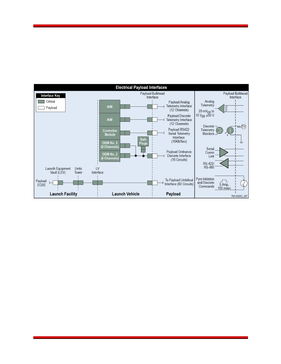
The payload electrical interface, shown in Figure 5.3-1, supports battery charging, external power,
discrete commands, discrete telemetry, analog telemetry, serial communication, SV separation
indications, and up to 16 separate ordnance discretes. If an optional Orbital-provided separation system
is utilized, Orbital will provide all the wiring through the separable interface plane. If the option is not
exercised the spacecraft will be responsible to provide the separation connectors and wiring through the
separation plane.
Figure 5.3-1. Payload Electrical Interface Block Diagram Payload Interface Circuitry
5.3.1. Payload Umbilical Interfaces
One dedicated payload umbilical is provided with 60 circuits from the ground to the spacecraft. This
umbilical is a dedicated pass through harness for ground processing support. This umbilical allows the SV
command, control, monitor, and power to be easily configured per each individual user’s requirements.
The umbilical wiring is configured as a one-to-one from the Payload/Minotaur interface through to the
payload EGSE interface in the Launch Equipment Vault, the closest location for operating customer
supplied EGSE equipment. The length of the internal umbilical is approximately 13.7 m (45 ft). The length
of the external umbilical from the LEV/SEB to the launch vehicle is approximately 35.1 m (115 ft) to 96.0
m (315 ft) depending on the launch site chosen for the mission.
Figure 5.3.1-1 details the pin outs for the standard interface umbilical. All wires are twisted, shielded
pairs, and pass through the entire umbilical system, both vehicle and ground, as one-to-one to simplify
and standardize the payload umbilical configuration requirements while providing maximum operational
flexibility to the payload provider.
Release 3.0
March 2014
40