Payload access door – Orbital Minotaur I User Manual
Page 43
Minotaur I User’s Guide
Section 5.0 – Payload Interfaces
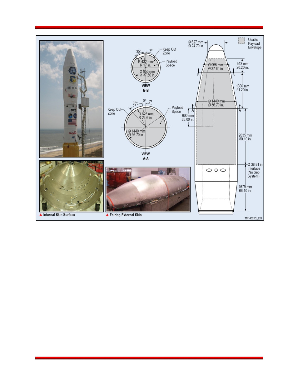
Figure 5.1.2.1-1. 61” Payload Fairing Dynamic Envelope with
38” (97 cm) Diameter Payload Interface
No part of the payload may extend aft of the payload interface plane without specific Orbital approval.
Incursions to these zones may be approved on a case-by-case basis after additional verification that the
incursions do not cause any detrimental effects. Vertices for payload deflection must be given with the
Finite Element Model to evaluate payload dynamic deflection with the CLA. The payload contractor
should assume that the interface plane is rigid; Orbital has accounted for deflections of the interface
plane. The CLA will provide final verification that the payload does not violate the dynamic envelope.
5.1.3. Payload Access Door
On the standard 50” fairing, Orbital provides one 254 mm by 368 mm (10.00 in. by 14.50 in.) payload
fairing access door to provide access to the payload after fairing mate. The door can be positioned
according to user requirements within the zone defined in Figure 5.1.3-1. The position of the payload
fairing access door must be defined no later than L-8 months. Additional access doors can be provided as
a non-standard service (see Section 8.4). Access doors on the optional 61” fairing are limited to 254 mm
by 279 mm (10.00 in. by 11.00 in.) and can be positioned within the zone defined in Figure 5.1.3-2.
Release 3.0
March 2014
30