Payload vibration environment, Payload acoustic environment, Payload shock environment – Orbital Minotaur I User Manual
Page 36: Minotaur i user’s guide
Minotaur I User’s Guide
Section 4.0 – Payload Environment
4.2. Payload Vibration Environment
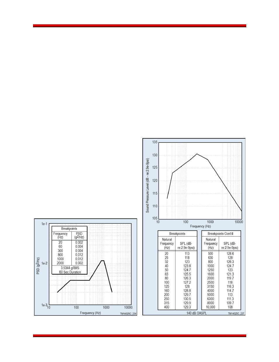
The in-flight random vibration curve shown in Figure 4.2-1 encompasses all flight vibration environments.
4.3. Payload Acoustic Environment
The acoustic levels during lift-off and powered flight will not exceed the flight limit levels shown in Figure
4.3-1. If the vehicle is launched over a flame duct, the acoustic levels can be expected to be lower than
shown. This has been demonstrated with flight data.
4.4. Payload Shock Environment
The maximum shock response spectrum at the base of the payload from the launch vehicle will not
exceed the flight limit levels in Figure 4.4-1 (LV to Payload). For missions that utilize an Orbital-supplied
separation system, the maximum expected shock (LV to Payload) will be the level shown for the chosen
separation system. For missions that do not utilize an Orbital-supplied separation system, the maximum
expected shock (LV to Payload) is provided and denoted as "Stage 3/4 Separation Shock at Payload I/F".
For all missions, the shock response spectrum at the base of the payload from payload events should not
exceed the levels in Figure 4.4-2 (Payload to LV). Shock above this level could require requalification of
launch vehicle components.
4.5. Payload Structural Integrity and
Environments Verification
The payload must possess sufficient strength,
rigidity, and other characteristics required to
survive the handling and flight load conditions with
margin in a manner that assures both safety and
mission success.
Sufficient payload testing and/or analysis must be
performed to show adequate margin to the
environments and loads specified in Sections 4.1
Figure 4.3-1. Payload Acoustic Environment
during Liftoff and Flight
Figure 4.2-1. Payload Random Vibration
Environment during Flight
Release 3.0
March 2014
23