Payload mechanical interface and separation system, Minotaur coordinate system – Orbital Minotaur I User Manual
Page 45
Minotaur I User’s Guide
Section 5.0 – Payload Interfaces
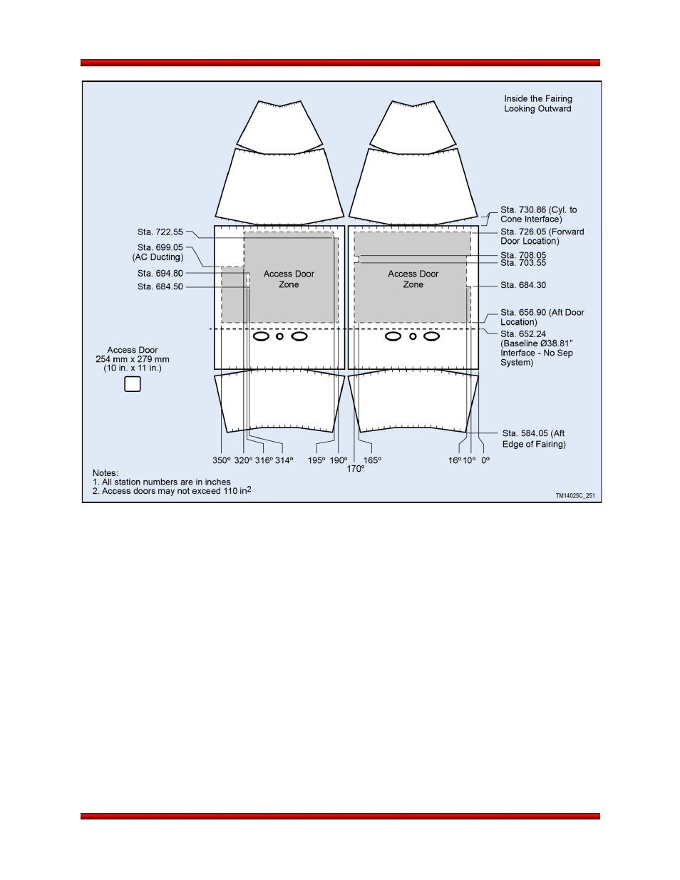
Figure 5.1.3-2. 61” Payload Fairing Access Door Placement Zone
5.2. Payload Mechanical Interface and Separation System
Minotaur I provides for a standard non-separating payload interface and several optional Orbital-provided
payload separation systems. Orbital will provide all flight hardware and integration services necessary to
attach non-separating and separating payloads to Minotaur I. Ground handling equipment is typically the
responsibility of the payload contractor. All attachment hardware, whether Orbital or customer provided,
must contain locking features consisting of locking nuts, inserts or fasteners. Additional mechanical
interface diameters and configurations can readily be provided as an enhanced option.
5.2.1. Minotaur Coordinate System
The Minotaur I Launch Vehicle coordinate system is defined in Figure 5.2.1-1. For clocking references,
degree marks are clockwise when aft looking forward. The positive X-axis is forward along the vehicle
longitudinal centerline, the positive Z axis is along the 180 deg angular azimuth, and the positive Y axis is
along the 90 deg angular azimuth, and completes the orthogonal system. The origin of the LV coordinate
system is centered at the Stage 1 nozzle exit plane of the LV and the vehicle centerline (X = 0.0 in, Y =
0.0 in, Z = 0.0 in).
Release 3.0
March 2014
32