Omnitron Systems Technology iConverter 5-Module Chassis User Manual
Page 6
Page 6
If rack mounting, mount and attach the chassis (after the mounting brackets are installed) to the rack using the appropriate rack
mounting screws (not provided).
Locate the DC circuit breaker and switch the circuit breaker to the OFF position.
Prepare a power cable using a three conductor insulated wire (not supplied) with a 14 AWG gauge. Cut the power cable to
the length required.
Strip approximately 3/8 of an inch of insulation from the power cable wires.
Connect the power cables to the chassis by fastening the stripped ends to the DC power connector.
WARNING: Note the wire colors used in making the positive, negative and ground connections. Use the same color assignment
for the connection at the circuit breaker.
Connect the power wires to the circuit breaker and switch the circuit breaker ON. The fans should immediately begin to run
and any installed modules will illuminate the power LEDs.
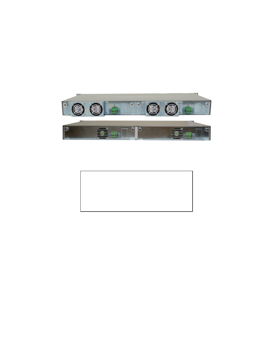
Figure 5:
iConverter
5-Module Chassis with Installed DC Power Supplies
4.0
POWER SUPPLY REPLACEMENT
CAUTION: To remove power from the chassis, remove the power cord from all power supplies.
WARNING!!!
NEVER ATTEMPT TO OPEN THE CHASSIS OR SERVICE THE
POWER SUPPLY OR FAN MODULE. OPENING THE CHASSIS
MAY CAUSE SERIOUS INJURY OR DEATH.
THERE ARE NO USER REPLACEABLE OR SERVICEABLE
PARTS IN THIS UNIT.
The power supplies are hot swappable and can be replaced without shutting the chassis down. However, when removing
and replacing a power supply unit, the following steps must be strictly followed in order to prevent serious injury or death
or serious damage to your equipment. Removal of power supplies or cards will result in access to hazardous electrical.
4.1
Hot Removal of AC Power Supply
Determine which power supply is faulty by observing the status LEDs on the back of the power supply (8221-2 only) or viewing
the status using the
iConverter
NMM2 and network management software. When viewing the LEDs on the NMM2, PSx
LED OFF indicates power supply “x” is not present, PSx LED blinking indicates power supply “x” is installed but not powered
and PSx ON indicates power supply “x” is powered. When viewing the LED on the back of the power supply, a yellow LED
indicates the power supply is installed but not powered and both fans are ON. A blinking yellow LED indicates the power
supply is installed but not powered and only one fan or neither fan is ON. A green LED indicates the power supply is installed
and powered with both fans ON.
Power Supply 1 (PS1) refers to the power supply on the right (as viewed from the front). Power Supply 2 (PS2) refers to the
power supply on the left.
Once you determine that your AC plug is connected properly to an AC wall outlet, and the power supply LED is still not ON,
determine which is the failing power supply unit and proceed to the next step.
Remove the AC power cord of the faulty power supply from the wall outlet.
Remove the AC power cord of the faulty power supply from the power supply unit.
Using a screwdriver, loosen the 2 thumb screws securing the power supply to the main chassis (refer to Figure 4).
Remove the failing power supply.