Iconverter, Module power chassis user manual – Omnitron Systems Technology iConverter 5-Module Chassis User Manual
Page 3
Page 3
iConverter
5-Module Power Chassis
User Manual
1. 0 GENERAL DESCRIPTION
The
iConverter
1U (1.75 inch) 5-Module Power Chassis is powered by up to two (2) hot-swappable and redundant universal AC
or DC power supplies and can accommodate up to 5
iConverter
modules. It is ideal for enterprise Local Area Network (LAN) or
Metropolitan Area Network (MAN) applications where managed media converters with high density and small rack-footprint are
important.
Figure 1:
iConverter
5-Module Chassis (Shown without modules installed)
This User Manual describes the following models:
Configuration
5-Module Chassis
AC
(33 watts)
AC
High Airflow
(66 watts)
24VDC
(33 watts)
48VDC
(33 watts)
48VDC
High Airflow
(66 watts)
One (1) Power Supply
8220-1
-
8226-1
8225-1
-
Two (2) Power Supplies
8220-2
8221-2
8226-2
8225-2
8227-2
Spare Power Supply
8220-9
8221-9
8226-9
8225-9
8227-9
23” Rack Mount Kit
8092-2
Blank Module Panel
8090-0
For wide temperature (-40 to 60° C) add a “W” to the end of the model number. Consult factory for
extended temperature (-40 to 75° C) models.
1.1
Mechanical Description
The
iConverter
5-Module chassis consists of two AC or DC power supplies. As can be seen from the model table above, the
5-Module chassis models have been pre-configured with two power supplies. The power supplies provide power to the chassis’
5 backplane connectors.
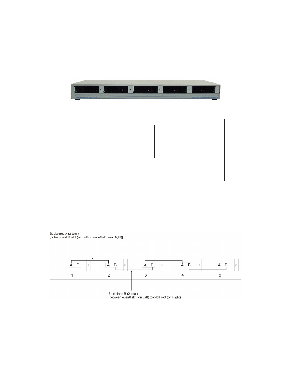
1.2
Backplane Architecture
The chassis features 5 module slots numbered 1 (left-most positioned slot) through 5 (right-most positioned slot).
Backplane A and Backplane B provide Ethernet connectivity between adjacent slots.
Figure 2:
iConverter
5-Module Chassis Backplane Architecture
Figure 2 depicts the backplane architecture of the chassis showing Backplane A and Backplane B connectivity.
Backplane A connects odd numbered slots on the left to even numbered slots on the right (i.e. 1-2, 3-4).
Backplane B connects even numbered slots on the left to odd numbered slots on the right (i.e. 2-3, 4-5).
When modules with Backplane capabilities are inserted into adjacent chassis slots, they can connect to each other via the Ethernet
backplanes when enabled, creating a flexible network architectures.
This chassis architecture facilitates a variety of applications including unmanaged, in-band managed and multi-port configurations.