Str46spvg — maintenance (trowel) – Multiquip STR46SPVG User Manual
Page 33
STR46SPVG • RIDE-ON POWER TROWEL — OPERATION AND PARTS MANUAL — REV. #2 (07/09/07) — PAGE 33
Re-Assembly
1. Clean and examine the upper/lower wear plates and
thrust collar. Examine the entire spider assembly. Wire
brush any concrete or rust build-up. If any of the spider
components are found to be damaged or out of round,
replace them.
2. Make sure that the bronze trowel arm bushing is not
damage or out of round. Clean the bushing if necessary.
If the bronze bushing is damage or worn, replace it.
3. Reinstall bronze bushing onto trowel arm.
4. Repeat steps 2 -3 for each trowel arm.
5. Make sure that the spring tensioner is in the correct
position to exert tension on the trowel arm.
6. Insert all trowel arms with levers into spider plate (with
bronze bushing already installed) using care to align
grease hole on bronze bushing with grease hole fitting on
spider plate.
7. Lock trowel arms in place by tightening the hex head zerk
grease fitting and jam nut.
8. Re-install the blades back onto the trowel arms
8. Install stabilizer ring onto spider assembly.
9. Reinstall lower wear plate,
thrust collar and upper
wear ring in the reverse order that they were dis-
assembled onto the spider shaft. Make sure that there is
little or no lateral movement between the thrust collar and
the spider shaft.
10. Lubricate all grease points (zerk fittings) with premium
"
Lithum 12" based grease, conforming to NLG1 Grade
#2 consistency.
Blade Pitch Overview
Sometimes it may be necessary to match blade pitch
between the two sets of blades. There are some signs that
this may be necessary. For example, the differences in pitch
could cause a noticeable difference in finish quality between
the two sets of blades. Or, the difference in blade pitch could
make the machine difficult to control. This is due to the surface
area in contact with the concrete (the blade set with the
greater contact area tends to stick to the concrete more).
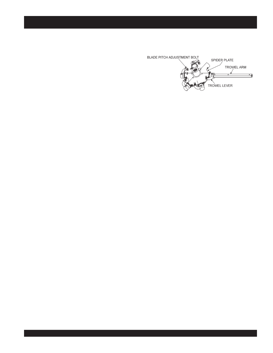
The maintenance adjustment of blade pitch is an adjustment
that is made by a bolt (Figure 30) on the arm of the trowel
blade finger.
STR46SPVG — MAINTENANCE (TROWEL)
This bolt is the contact point of the trowel arm to the lower
wear plate on the thrust collar. The goal of adjustment is to
promote consistent blade pitch and finishing quality.
There are some things to look for when checking to see if
adjustment is necessary. Is the machine wearing out blades
unevenly (i.e. one blade is completely worn out while the
others look new)? Does the machine have a perceptible
rolling or bouncing motion when in use? Look at the machine
while it is running, do the guard rings “rock up and down”
relative to the ground? Do the pitch control towers rock back
and forth? These are some of the indications that the blade
pitch may need to be adjusted using the adjustment bolts
on the trowel blade finger.
The easiest and most consistent way to make this adjustment
is to use the Trowel Arm Adjustment Fixture (P.N. 9177).
See Figure 30. This fixture will allow consistent adjustment
of the trowel arm fingers. It comes with all the hardware
necessary to properly accomplish this maintenance and
instructions on how to properly utilize this tool. Adjusting
the trowel arm fingers without a fixture requires a special
talent.
If a trowel arm adjustment fixture is not available and
immediate adjustment is necessary; we suggest the following
procedure. If you can see or feel which blade is pulling harder,
adjust the bolt that corresponds to that blade.
Another way to determine which blades need adjustment is
to place the machine on a flat surface and pitch the blades
as flat as possible. Now, look at the adjustment bolts. They
should all barely make contact with the lower wear plate on
the spider. If you can see that one of them is not making
contact; some adjustment will be necessary.
It will be possible to adjust the “high” bolts down to the level
of the one that is not touching, or adjust the “low” bolt up to
the level of the higher ones. If possible, adjust the low bolt
up to the level of the rest of the bolts. This is the fastest
way, but may not always work. Verify that after adjustment,
the blades pitch correctly.
Figure 30. Blade Pitch Adjustment Bolt