Str46spvg — maintenance (trowel) – Multiquip STR46SPVG User Manual
Page 31
STR46SPVG • RIDE-ON POWER TROWEL — OPERATION AND PARTS MANUAL — REV. #2 (07/09/07) — PAGE 31
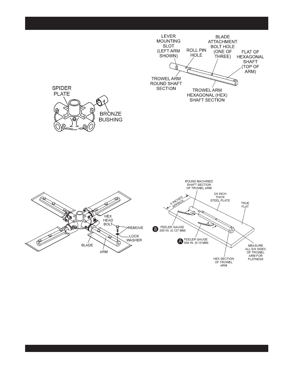
Trowel Arm Flatness Test
1. Using a piece of 3/4 inch thick steel plate or any surface which
is
true
and
flat
, check all
six sides
of each trowel arm for
flatness.
2. Check each of the six sides of the trowel arm (hex section).
A feeler gauge of .004" (0.10 mm) should not pass between
the flat of the trowel arm and the test surface along its length
on the test surface (Figure 46, A) .
Figure 27. Trowel Arm Flatness Test
3. Should the trowel arm inserts (bronze bushing ) come out
with the trowel arm, remove the bushing from the trowel arm
and set aside in a safe place. If the bushing is retained inside
the spider plate, carefully remove the bushing.
4. Examine the bronze trowel arm bushing insert (Figure 24),
clean if necessary. Replace bushing if out-of-round or worn.
Figure 24. Bronze Bushings
Trowel Blade Removal
1. Remove the trowel blades from the trowel arm by removing
the three hex head bolts (Figure 25) from the trowel arm. Set
blades aside.
Figure 25. Trowel Blades
2.
Wire brush
any build-up of concrete from all six sides of the
trowel arm. Repeat this for the remaining three arms.
STR46SPVG — MAINTENANCE (TROWEL)
Checking Trowel Arm Straightness
Trowel arms can be damaged by rough handling, (such as
dropping the trowel on the pad), or by striking exposed
plumbing, forms, or rebar while in operation. A bent trowel
arm will not allow the trowel to operate in a smooth fluid
rotation. If bent trowel arms are suspect, check for flatness
as follows, refer to Figures 26 and 27.
Figure 26. Typical Trowel Arm
3. Next, check the clearance between the round shaft and
the test surface as one of the flat hex sections of the arm
rests on the test surface. Rotate the arm to each of the
flat hex sections and check the clearance of the round
shaft. Use a feeler gauge of .005" (0.127 mm). Each
section should have the
same clearance between the
round of the trowel arm shaft and the test surface (Figure
27, B) .