Str46spvg — maintenance (trowel) – Multiquip STR46SPVG User Manual
Page 32
STR46SPVG • RIDE-ON POWER TROWEL — OPERATION AND PARTS MANUAL — REV. #2 (07/09/07) — PAGE 32
Trowel Arm Adjustment
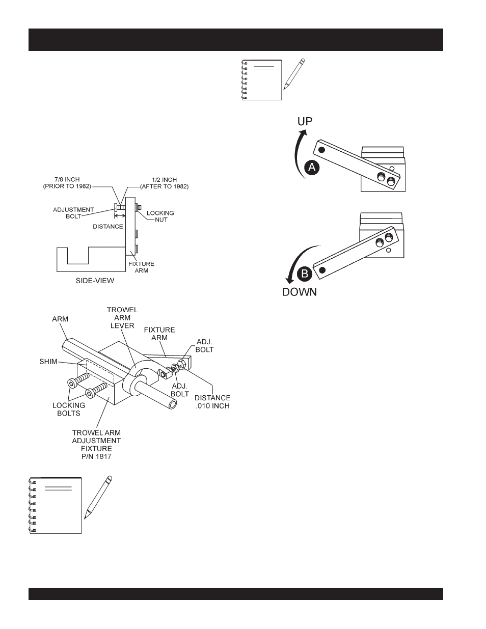
Shown in Figure 28 is the adjustment fixture with a trowel arm
inserted. As each trowel arm is locked into the fixture, the
arm bolt is adjusted to where it contacts a stop on the fixture.
This will consistently adjust all of the trowel arms, keeping
the finisher as flat and evenly pitched as possible.
1. Locate the trowel arm adjustment tool P/N 9177.
2. Ensure the fixture arm is in the proper position (up or
down) for your trowel arm rotation as shown in Figure 29.
Figure 28. Trowel Arm
Adjustment Tool
STR46SPVG — MAINTENANCE (TROWEL)
The distance from the end of the
adjusting bolt and the fixture arm
must be 1/2".
Arms with CLOCK-WISE blade rotation use
the fixture arm in the UP position (A in Figure
39). Arms with COUNTER CLOCK-WISE
blade rotation use the fixture with the fixture
arm in the DOWN position. (B in Figure 29)
NOTE
Figure 29. Trowel Arm Adjustment Setup
3. Un-screw the locking bolts on the adjustment tool, and
place the trowel arm into the adjustment fixture channel
as shown in Figure 28. A
thin shim may be required to
cover the blade holes on the trowel arm. Make sure to
align the trowel adjustment bolt with the fixture adjust-
ment bolt.
4. Adjust the bolt "distance" shown in Figure 28 to match
one of the arms. The other arms will be adjusted to match
this distance.
5. Using an allen wrench, tighten the locking bolts on the
adjustment tool and securely lock the trowel arm in
place.
6. Loosen the locking nut on the trowel arm lever, then turn
the trowel arm adjusting bolt until it barely touches
(.010") the adjusting bolt on the fixture.
7. After the correct adjustment has been made, tighten lock
nut on trowel arm lever to lock in place.
8. Loosen locking bolts on adjustment fixture, and remove
trowel arm from fixture.
9. Repeat steps 2-8 for the remaining trowel arms.
NOTE