Str46spvg — controls and indicators – Multiquip STR46SPVG User Manual
Page 19
STR46SPVG • RIDE-ON POWER TROWEL — OPERATION AND PARTS MANUAL — REV. #2 (07/09/07) — PAGE 19
STR46SPVG — CONTROLS AND INDICATORS
20. Kill Switch – Shuts down engine when operator is not
sitting in seat .
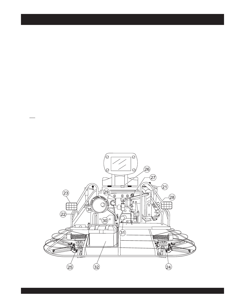
21. Radiator/Filler Cap – Holds coolant or water necessary to
keep engine at a safe operating temperature. Remove this
cap to add water or antifreeze.
22. Lift Loops – Located on both the left and right sides of the
main frame. Used when the trowel must be lifted onto a
concrete slab.
23. Lights – Four 12 volt halogen lights are provided with this
unit.
24. Right-Side Spider – Consists (basic) of trowel arms,
blades, wear plate, and thrust collar etc.
25. Left-Side Spider – Consists (basic) of trowel arms, blades,
wear plate, and thrust collar etc.
26. Safety Kill Switch – Shuts down engine when operator is
not sitting in seat.
Figure 3. STR46SPVG Controls and Indicators (Rear)
27. Engine Oil Filler Cap - Remove this cap to add engine oil.
28. Overflow Bottle - Supplies coolant to the radiator when
radiator coolant level is low. Fill to indicated level as
shown on bottle.
29. Engine Air Filter – Prevents dirt and other debris from
entering the fuel system. Lift locking latch on air filter
cannister to gain access to filter element.
30. Engine Dip Stick – Indicates engine oil level. Add oil as
required.
31. Oil Filter – Provides oil filtering for the engine.
32. Battery – Provides +12V DC power to the electrical system
35. Belt Guard – Encloses V-belts used in conjunction with
clutch.
The following section is intended as a basic guide to the ride-on
trowel operation, and is not to be considered a complete guide
to concrete finishing. It is strongly suggested that all operators
(experienced and novice) read “
Slabs on Grade
” published by
the American Concrete Institute, Detroit Michigan.