Str46spvg — maintenance (trowel) – Multiquip STR46SPVG User Manual
Page 30
STR46SPVG • RIDE-ON POWER TROWEL — OPERATION AND PARTS MANUAL — REV. #2 (07/09/07) — PAGE 30
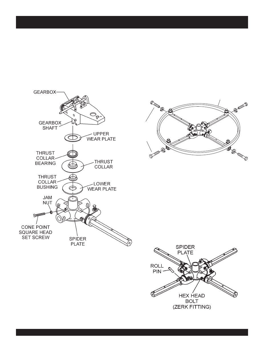
a. Locate cone point square head set screw (Figure 21)
and attached jam nut found on the side of the spider
assembly.
Spider Removal (Disassembly)
1. Once it is determined that an adjustment is required,
remove the spider assembly from the gearbox shaft as
follows:
Figure 21. Spider/Gearbox Removal
b. Loosen the jam nut and cone point square head set
screw, and carefully lift the
upper trowel assembly
off
of the spider assembly. A slight tap with a rubber mallet
may be necessary to dislodge the spider from the main
shaft of the gearbox.
c.
If the trowel is equipped with an outer stabilizer ring
(Figure 21), remove the four bolts at the end of each
spider arm.
Figure 22. Stabilizer Ring
d. Examine stabilizer ring for out of round or bends. If ring
is damaged, replace ring. If ring is found to be correct with
no damage, set aside.
Trowel Arm Removal
1. Each trowel arm is held in place at the spider plate by a hex
head bolt (zerk grease fitting) and a roll pin. Remove both the
hex head bolt and the roll pin (Figure 23) from the spider
plate.
2. Remove the trowel arm from the spider plate.
Figure 23. Removing Roll Pin
and Zerk Grease Fitting
STABILIZER
RING
REMOVE
TO FREE
SPIDER
ASSEMBLY
STR46SPVG — MAINTENANCE (TROWEL)