Str46spvg — maintenance (trowel) – Multiquip STR46SPVG User Manual
Page 29
STR46SPVG • RIDE-ON POWER TROWEL — OPERATION AND PARTS MANUAL — REV. #2 (07/09/07) — PAGE 29
Figure 19. Worn Spider Plate
Trowel Arm Adjustment Procedure
The following procedure should be
followed to adjust trowel arms when
it becomes apparent that the trowel
is finishing poorly or in need of
routine maintenance.
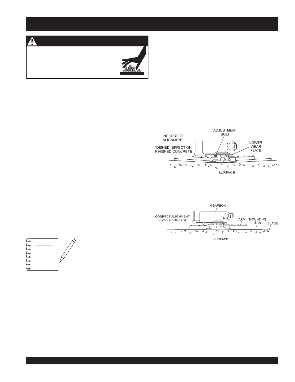
■ Pitch the blades as flat as possible and look at the
adjustment bolts
. They should all barely make contact with
the
lower wear plate
on the spider. If you can see that one of
them is not making contact, some adjustment will be
necessary.
■ Is the machine wearing out blades unevenly (i.e. one blade
is completely worn out while the others look new)?
Figure 19 below illustrates a "
worn spider bushings or bent
trowel arms
". Check to see that adjustment bolt is barely
touching (0.10" max. clearance) lower wear plate. All alignment
bolts should be spaced the same distance from the lower wear
plate.
Figure 20 below illustrates the "
correct alignment
" for a spider
plate (as shipped from the factory).
Figure 20. Correct Spider Plate Alignment
NOTE
ALWAYS allow the engine to cool before
servicing. NEVER attempt any maintenance
work on a
hot!
engine.
WARNING - BURN HAZARDS
Trowel Maintenance Schedules
Weekly (50-60 Hours)
1.
Relube arms, thrust collar and clutch.
2.
Replace blades if necessary.
Monthly (200-300 Hours)
1.
Remove, clean, reinstall and relube the arms and thrust
collar. Adjust the blade arms.
2.
Replace gearbox lubricant after the first 100 hours of
operation. Replace every 500-600 hours thereafter.
3.
Check drive belt for excessive wear. (Refer to following
section on Drive Belt maintenance.)
4.
Remove, clean, reinstall clutch.
Yearly (2000-2500 Hours)
1.
Check and replace if necessary the arm bushings, and
thrust collar bushings, shaft seals and belts.
2.
Check pitch control cables for wear.
3.
Replace gearbox lubricant.
A
level, clean area to test the trowel prior to and after is
essential. Any uneven
spots in the floor or debris under the
trowel blades will give an incorrect perception of adjustment.
Ideally, a 5-foot by 5 foot three-quarter inch thick
flat steel
plate should be used for testing.
To determine which blades need adjustment, place the trowel
in the test area (three-quarter inch thick plate) and look for
the following conditions:
STR46SPVG — MAINTENANCE (TROWEL)
Start engine, and bring trowel blades up to full speed and look
for the following conditions:
■ Does the trowel have a perceived rolling or bouncing
motion when in use?
■ Look at the trowel while it is running, does the guard ring
“rock up and down” relative to the ground?