Assembly – Multiquip WSHE_A_SERIES User Manual
Page 27
WSHe/a vibraTory TruSS Screed • operaTion manual — rev. #0 (05/22/12) — page 27
aSSeMbly
The illustrations referenced in this section describe how
to assemble the vibratory screed. Listed below are the
various assemblies that will have to be assembled. End
Handle Section
engine Section
Truss Frame Section
Hand Winch Section
TruSS Screed Frame orienTaTion
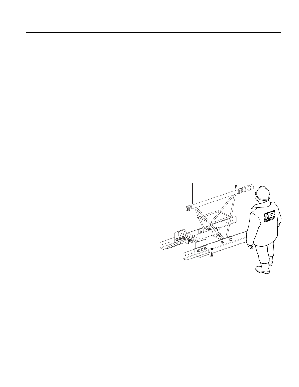
Figure 14 shows how to determine the left, right, front and
rear of a screed frame truss section.
The right side of the screed truss frame will be stamped
with the letter "R" and the left side will be stamped with the
letter "L". In addition the front of the screed will have two
screed blades attached to the truss frame, while the rear
of the truss frame has only one bullfloat blade.
Figure 14. Screed Orientation
RIGHT
LEFT
FRONT
REAR
R
L
STAMPING
STAMPING
2 BLADES
aSSembly
alWayS assembled screed on a flat surface that is free of
debris and foreign objects. For best result place screed on
a flat platform during assembly. This will ensure flatness of
the screed blades when assembly is complete.
Things to remember during and after assembly:
• alWayS make sure eccentric drive shaft is properly
aligned.
• Make sure eccentric weights are installed correctly.
Reference Figure 35 for correct orientation.
• If eccentric weights are mismatched screed will not
vibrate properly.
• do noT overspeed, engine speed must not exceed
3600 RPM.
• never let concrete build on front blade. This condition
causes the screed to be stressed and make turning of
the winch handles difficult.
• do noT over vibrate concrete.
• Turn winch handles simultaneously to keep screed
even.