Components – Multiquip WSHE_A_SERIES User Manual
Page 21
WSHe/a vibraTory TruSS Screed • operaTion manual — rev. #0 (05/22/12) — page 21
cOMpOnentS
1
2
14
13
15
13
15
17
18
16
5
6
9
3
3
12
8
7
4
10
11
11
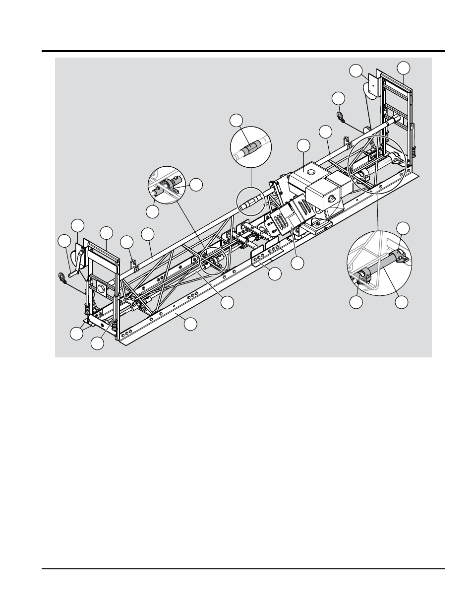
Figure 5 and Figure 6 show the location of the basic
components of a 10-foot WSHE/A screed. The function of
each component is described below.
1.
rear (bull Float) blade — 2-1/2" high x 3" wide blade,
constructed of 10-gauge galvanized steel.
2.
Front blades — two 2-1/2" high x 2" wide blades,
constructed of 10-gauge galvanized steel.
3.
Truss Frame — Available in four lengths: 2-1/2 ft., 5 ft.,
7-1/2 ft. and 10 ft. (two 5 ft. sections illustrated above).
Each frame section features a heavy-duty schedule 80
top pipe for structural integrity.
4.
Turnbuckle — Connects two truss sections together.
Fine threads allow controlled adjustment for slight
crown or invert configurations.
5.
blade connector — Connects two blades together.
Bolt-on blade design allows for easy replacement of
worn or damaged blades.
6.
rotating eccentric Shaft — Produces over 8000
VPM, built of 3/4" diameter, high strength steel.
7.
pillow block bearings — Support rotating shaft.
8.
eccentric Weights — Bolted onto rotating shaft to
produce vibration.
9.
engine — Honda GX270 or GX340 engine drives the
rotating shaft.
10.
guard Tube — Covers the rotating shaft to prevent
equipment damage and operator injury.
11.
Tube mounts — Secure guard tubes to the truss frame.
12.
belt guard — Covers the rotating V-belt to prevent
operator injury.
Figure 5. WSHE Components