MTS Multi-Pump Control Manager User Manual
Page 37
Run On Demand Detailed Example
Multi-Pump Control Manager
Appendix
37
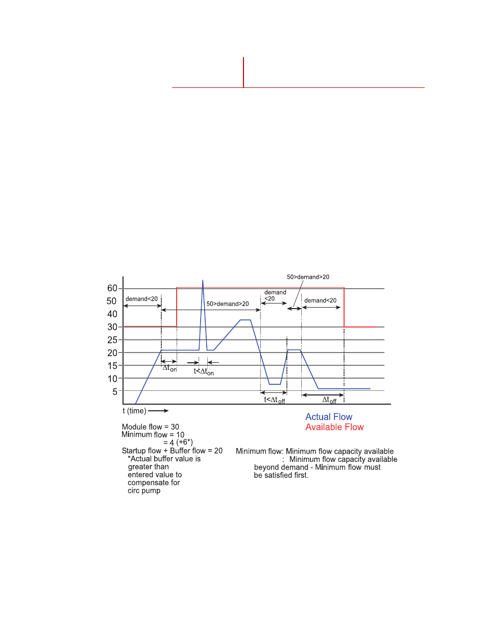
An example is shown below. In the example Module Flow is set at 30 gpm,
Minimum Flow is set at 10 gpm, Flow Buffer is set at 4 gpm (which means the
total actual buffer is 10 gpm), Δt
on
represents the on delay, and Δt
off
represents
off delay. The system starts out with one module running to create 30 gpm of
available flow. This satisfies both the Minimum Flow requirement (10 gpm) and
the Flow Buffer requirement (10 gpm). The demand rises and eventually hits 20
gpm. At this point the on delay is started because the 20 gpm of actual flow and
10 gpm of Flow Buffer meet or exceed the available 30 gpm. Because the flow
stays above 20 gpm for the length of time Δt
on
, another pump module is started
and available flow goes to 60 gpm. Then a spike occurs which exceeds the
available flow but because the duration of the spike is less than Δt
on
, another
pump module is not started. Flow then continues to increase but never exceeding
the next trigger point of 50 gpm for a duration of Δt
on
. Then flow drops off below
20 gpm. Because the flow does not stay below 20 gpm for the period of time
Δt
off
, no pump modules are turned off. Finally the flow tapers off and flow is
below 20 gpm for the time Δt
off
and the second pump module is turned off.
60 Hz
113 lpm
30 gpm
85 lpm
22 gpm
61 lpm
16 gpm
Flow buffer
Flow buffer