Spacing requirements, Cabling, Lifting instructions – MTS Multi-Pump Control Manager User Manual
Page 16: Ac power disconnect requirements, External device connections, Spacing requirements 16, Cabling 16, Lifting instructions 16, Ac power disconnect requirements 16, External device connections 16
Multi-Pump Control Manager
16
Spacing Requirements
Installation
Spacing Requirements
The front of the enclosure requires 65 cm (25.6 in) minimum of clearance so the
door can be opened by MTS service personnel. The power entry side of the
enclosure requires 16 cm (6.3 in) minimum of clearance for the power cord. The
bottom of the enclosure requires 65 cm (25.6 in) minimum of clearance for the
cables.
The dimensions above are minimum dimensions for the BCI. MTS recommends
an additional 1m (40 in) of clearance around the BCI to ease installation and
should service be necessary.
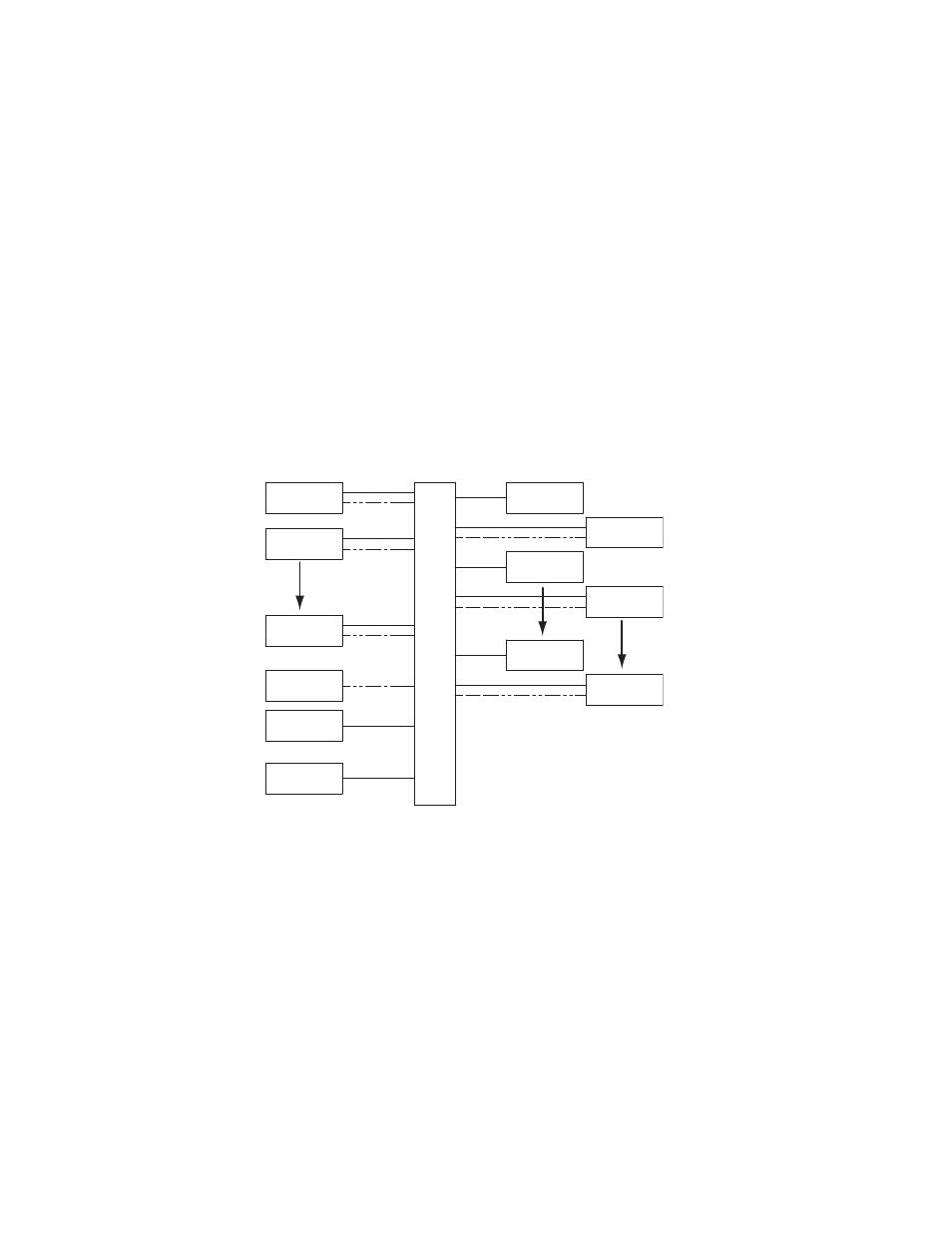
Cabling
Cabling consists of connecting the cables from all the associated components to
the BCI. Shown below is a block diagram of connections.
A detailed field wiring diagram (MTS Drawing number 700-005-779) can be
found on the Product Information CD.
Lifting Instructions
The MPCM weighs about 41 kg (90 lb). Improper lifting techniques can cause
strained muscles and back injuries. When lifting the MPCM, take the appropriate
precautions to prevent injuries to yourself.
AC Power Disconnect Requirements
Be sure to locate the MPCM so that you have adequate access to disconnect the
power cord from the unit.
External Device Connections
The MPCM is designed to work with MTS supplied devices. Only MTS supplied
devices should be connected to the MPCM.
HPU #2
HPU #1
E-STOP #1
E-STOP #2
E-STOP #8
SFM #1
SFM #7
SFM #8
OR
OR
OR
SUPERVISOR PC
LIGHT STACK(S)
SUPERVISOR
E-STOP
HPU #8
BCI
(DAISY CHAIN MULTIPLE LIGHT BARS,2 AMPS
PER CHANNEL NOT TO EXCEED 6 AMPS TOTAL)