Wiring according to emc (ce-typical drive system), Wiring according to emc (ce−typical drive system), Mechanical installation – Lenze E82MVxxx_4Bxxx User Manual
Page 85: Af x1, Kj i
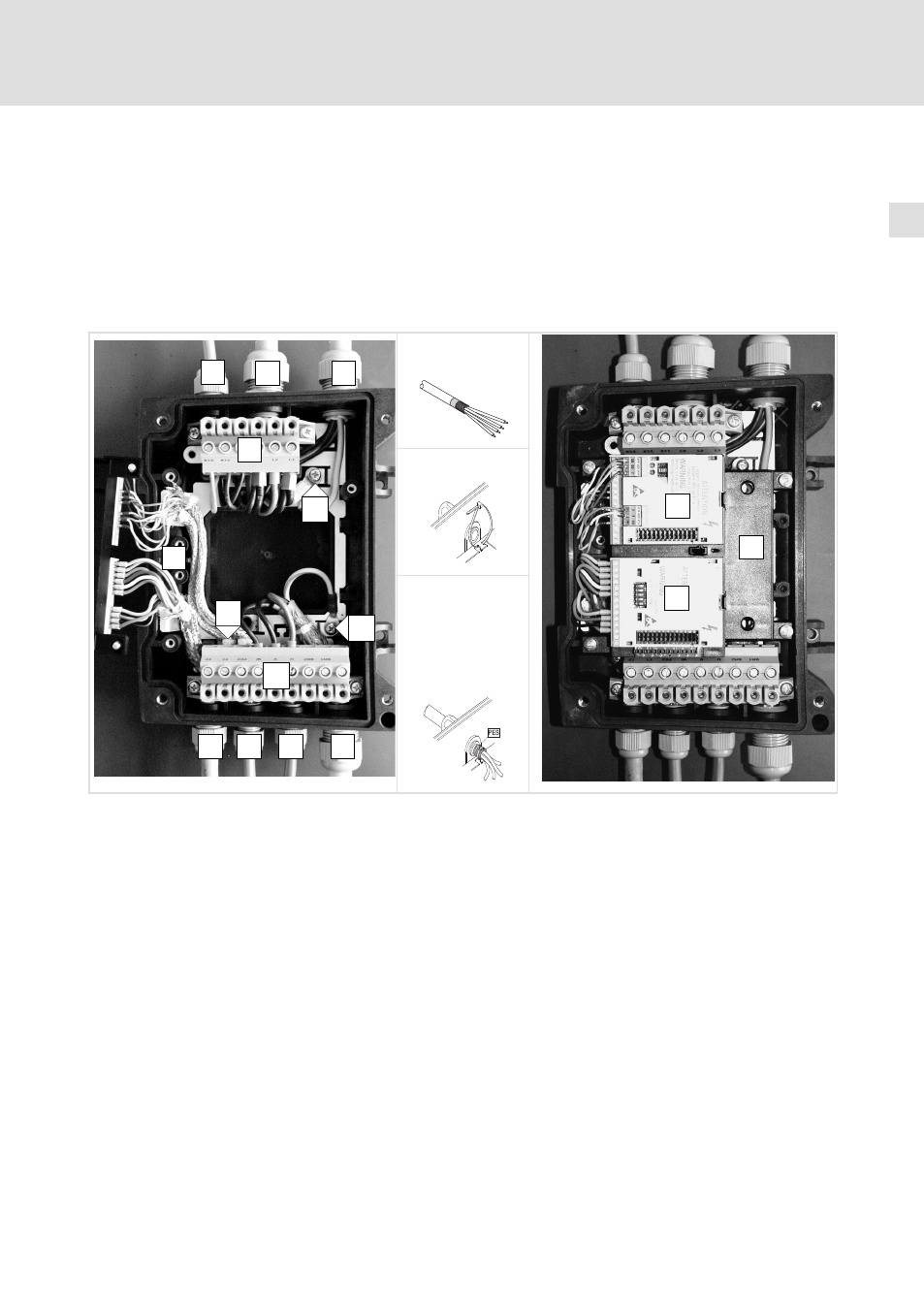
Mechanical installation
Wall mounting
Wiring according to EMC (CE−typical drive system)
l
85
EDK82MV752 DE/EN/FR 7.1
4.2.4
Wiring according to EMC (CE−typical drive system)
Conditions for trouble−free operation:
ƒ
Except for the mains cable, use shielded cables only.
ƒ
The shield must be carefully connected to PE (see below).
ƒ
Separate control and mains cables from motor cable!
ƒ
Connect motor and mains PE conductors to separate PE terminals.
A
F
X1
82mot398
B
B
C
D
E
F
F
G
X2
H
Shield connection:
1. Prepare the cable
82mot397
K
J
I
2. Insert the cable tie
3. Lay the cable into
the cable tie and
tighten it. The
shield must be
tightly connected
to the shield
sheet.
0
Relay connecting cable
X1
Terminal strip mains connection
1
Mains cables L1, L2, L3, PE (2 cables for loop−through
connection)
X2
Terminal strip motor connection
2
PE connection for mains cables
PES
HF−shield termination by large surface connection to PE
3
Shielded control cables; fix the shield tightly to the
sheet with the cable tie
4
PE connection of motor cable
5
Shielded control cables
6
Motor cable U, V, W (use low−capacitance motor cables!
^ 84)
7
Isolated terminal (e.g. star point for star connected
motor)
8
FIF support
9
Bus−I/O function module in slot 1
:
Fieldbus function module in slot 2