Technical data – Lenze 931W User Manual
Page 16
Technical data
Rated data
General data and operating conditions
3
16
GHB 13.0002-EN 3.1
3.3
Rated data
3.3.1
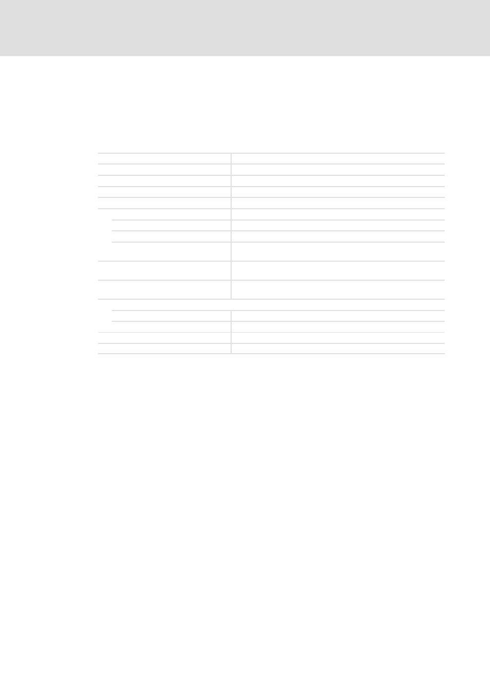
General data and operating conditions
The following standards and operating conditions are generally valid for 931M and
931W servo inverters:
Conformity
CE
Low-Voltage Directive 73/23/EEC
Regulations
Requirements in accordance with IEC/EN 61800-3 (category C3)
Climatic conditions
Air humidity max. 90 % without condensation
Cooling
Passively via housing surface and heatsink
Permissible temperature ranges
Transport
-25 °C... +70 °C
Storage
-25 °C... +70 °C
Operation
0 °C ... +40 °C
Internal ambient temperature
T
electronics
> 70 °C: Power derating
Disconnection at T
electronics
> 78 °C
Permissible installation height
0 ... 1000 m amsl
above 1000 m amsl, reduce the rated output
current by 5 %/1000 m
Mounting position
Every mounting position and mounting arrangement is permissible
(see restriction)
Mounting clearances
above/below
≥ 50 mm
sidewise
≥ 50 mm
Type of protection
IP 54
DC bus system
Possible with restrictions
Explanation: Restrictions for DC bus systems
ƒ
When supplying several 931M or 931W devices with DC voltage from a DC bus
system, ensure that the permissible voltage limits for the DC bus are observed when
power is consumed or fed back by the inverters.
ƒ
We recommend to use slow-blowing DC fuses to fuse inverters in larger DC bus
systems.
Explanation: restrictions concerning the mounting position
ƒ
In principle, every mounting position is permissible. The manufacturer recommends
a vertical arrangement of the cooling ribs of the heatsink. For mounting positions
with a non-vertical arrangement of the cooling ribs, the free convection is negatively
influenced. In this case, a power derating of the drive due to the decreased cooling
power may be required.
0 V (low) and 24 V (high) are used for the digital inputs and outputs. Here, the local CAN
communication is an exception, using a lower voltage level (5 V). The digital inputs and
outputs are short-circuit-proof, whereas the local CAN interface is not resistant to
short-circuits.
The functions of the digital I/Os are listed in the below table. For more information, please
see the Software Manual.