4 commissioning, 4 description of parameters – Lenze SCF frequency inverter User Manual
Page 36
36
Lenze 13466146 EDBSF01 v24 EN
4 Commissioning
4.4
Description of Parameters
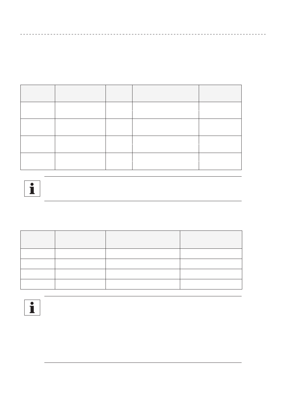
P01
LINE VOLTAGE SELECTION
This calibrates the drive for the actual applied input voltage, and can be set to HIGH (01) or LOW (02).
Refer to the table below for the proper setting depending on the input voltage.
MODEL
RATED INPUT
VOLTAGE
INPUT
PHASE
APPLIED INPUT
VOLTAGE
PARAMETER
SETTING
SF200Y
208 / 240 Vac
1 or 3
220 - 240 Vac
HIGH (01)
1 or 3
200 - 208 Vac
LOW (02)
SF200
208 / 240 Vac
3
220 - 240 Vac
HIGH (01)
3
200 - 208 Vac
LOW (02)
SF400
400 / 480 Vac
3
440 - 480 Vac
HIGH (01)
3
380 - 415 Vac
LOW (02)
SF500
480 / 590 Vac
3
575 - 600 Vac
HIGH (01)
3
460 - 480 Vac
LOW (02)
NOTE
If this parameter is changed while the drive is running, the new value will not take
effect until the drive is stopped.
P02
CARRIER FREQUENCY
This sets the switching rate of the output IGBT’s. Increasing the carrier frequency will result in less
audible motor noise. Available settings are: 4 kHz, 6 kHz, 8 kHz, and 10 kHz.
PARAMETER
SETTING
CARRIER
FREQUENCY
MAXIMUM OUTPUT
FREQUENCY (NOTE 1)
AMBIENT OR OUTPUT
DERATE (NOTE 2)
01
4 kHz
240.0 Hz (400.0 Hz)
50ºC or 100%
02
6 kHz
240.0 Hz (600.0 Hz)
50ºC or 100%
03
8 kHz
240.0 Hz (999.9 Hz)
43ºC or 92%
04
10 kHz
240.0 Hz (999.9 Hz)
35ºC or 82%
NOTE
• For drives with the High Output Frequency option, the carrier frequency also
determines the maximum output frequency (shown in parenthesis).
• The SCF drive is fully rated up to 6 kHz carrier frequency. If the 8 kHz or 10 kHz
carrier frequency is selected, the drive’s ambient temperature rating OR output
current rating must be de-rated to the value shown in the table above.
• If this parameter is changed while the drive is running, the change will not take
effect until the drive is stopped. Therefore, the allowable maximum frequency for
drives with the High Output Frequency option (see NOTE 1) will not change if the
carrier frequency is changed while the drive is running.