Technical data 2, 2 scf model designation code, 3 scf specifications – Lenze SCF frequency inverter User Manual
Page 11
Lenze 13466146 EDBSF01 v24 EN
11
Technical Data
2
2.2
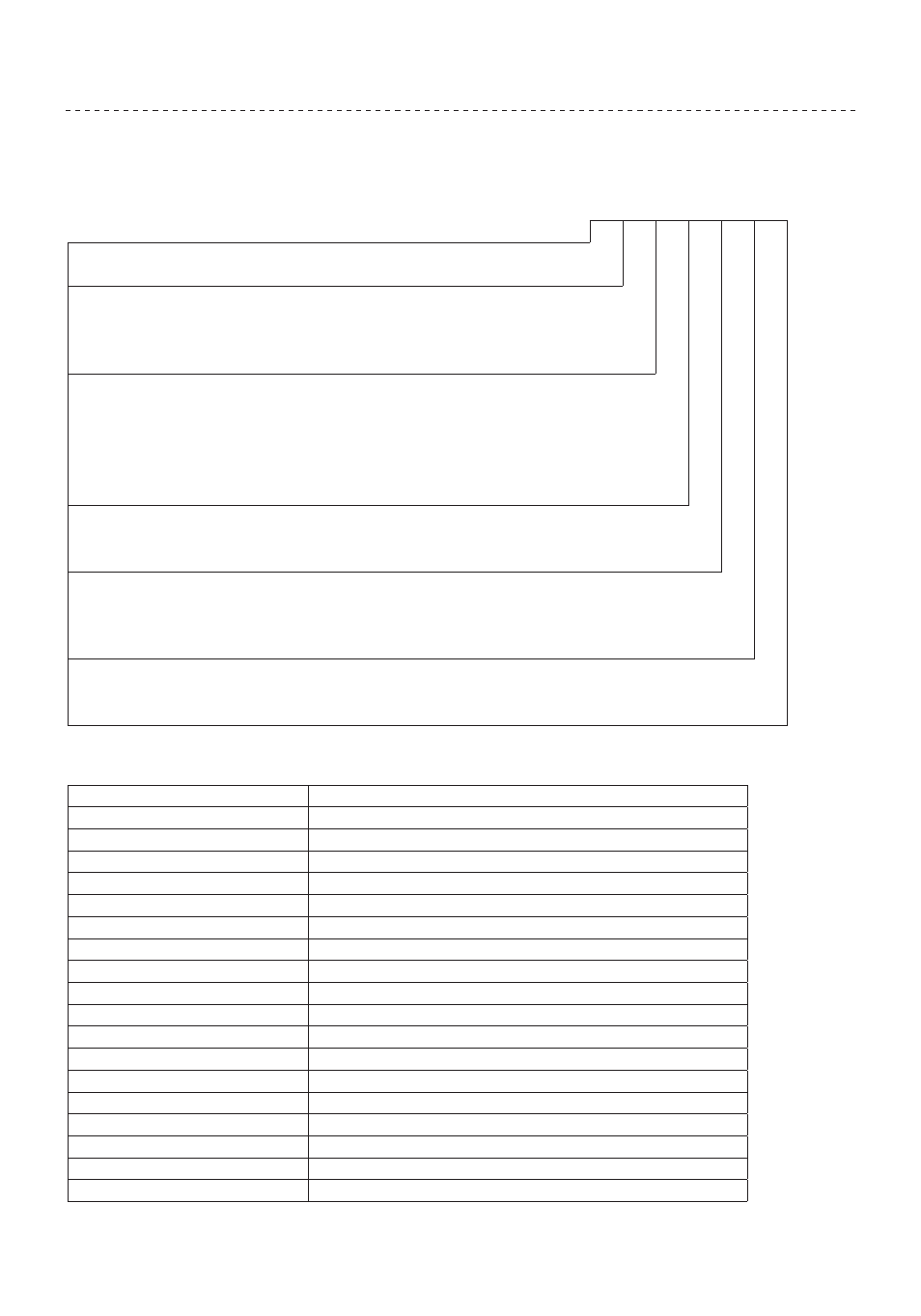
SCF Model Designation Code
The SCF model number gives a full description of the basic drive unit (see example below).
EXAMPLE: SF210Y (SCF Series, 208/240 Vac, 1 HP, single or three phase input)
SF
2 10 Y
Series:
SF
=
SCF Series Variable Speed AC Motor Drive
Input Voltage:
2
=
208/240 Vac (For 208, 230, and 240 Vac; 50 or 60 Hz)
4
=
400/480 Vac (For 380, 415, 440, 460 and 480 Vac; 50 or 60 Hz)
5
=
480/590 Vac (For 440, 460, 480, 575 and 600 Vac; 50 or 60 Hz)
Rating:
03
=
¼ HP (0.20 kW)
30
= 3 HP (2.2 kW)
200
= 20 HP (15 kW)
05
=
½ HP (0.37 kW)
50
= 5 HP (4.0 kW)
250
= 25 HP (18.5 kW)
10
=
1 HP (0.75 kW)
75
= 7½ HP (5.5 kW)
300
= 30 HP (22 kW)
15
=
1½ HP (1.1 kW)
100
= 10 HP (7.5 kW)
20
=
2 HP (1.5 kW)
150
= 15 HP (11 kW)
Input Phase:
Y
=
Single or three phase input.
No character indicates three phase input only
Mounting Style:
F
=
Through-hole mount with special heatsink
F1
=
Through-hole mount without heatsink (customer supplies heatsink)
No character indicates panel or DIN rail mounting
Application Specific Options:
P
=
PI (setpoint control) software
V
=
High Frequency Output - up to 1000 Hz
2.3
SCF Specifications
Storage Temperature
-20° to 70° C
Ambient Operating Temperature
0° to 50° C (derate 2.5% per °C above 50°)
Ambient Humidity
< 95% (non-condensing)
Maximum Altitude
3300 ft (1000 m) above sea level (derate 5% per additional 3300 ft)
Input Line Voltages
208/240 Vac, 400/480 Vac, 480/590 Vac
Input Voltage Tolerance
+10%, -15%
Input Frequency Tolerance
48 to 62 Hz
Output Wave Form
Sine Coded PWM
Output Frequency
0 - 240 Hz (consult factory for higher output frequencies)
Carrier Frequency
4 kHz to 10 kHz (over 6 kHz requires derating; see parameter P02)
Service Factor
1.00 (up to 6 kHz carrier; derate above 6 kHz; see parameter P02)
Efficiency
Up to 98%
Power Factor (displacement)
0.96 or better
Overload Current Capacity
150% for 60 seconds, 180% for 30 seconds
Speed Reference Follower
0-10 VDC, 4-20 mA
Control Voltage
15 VDC
Power Supply for Auxiliary Relays
50 mA at 12 VDC
Analog Output
0 - 10 VDC or 2 - 10 VDC: Proportional to frequency and load
Digital Outputs
Open-collector outputs: 50 mA at 30 VDC