Installation 3 – Lenze SCF frequency inverter User Manual
Page 27
Lenze 13466146 EDBSF01 v24 EN
27
Installation 3
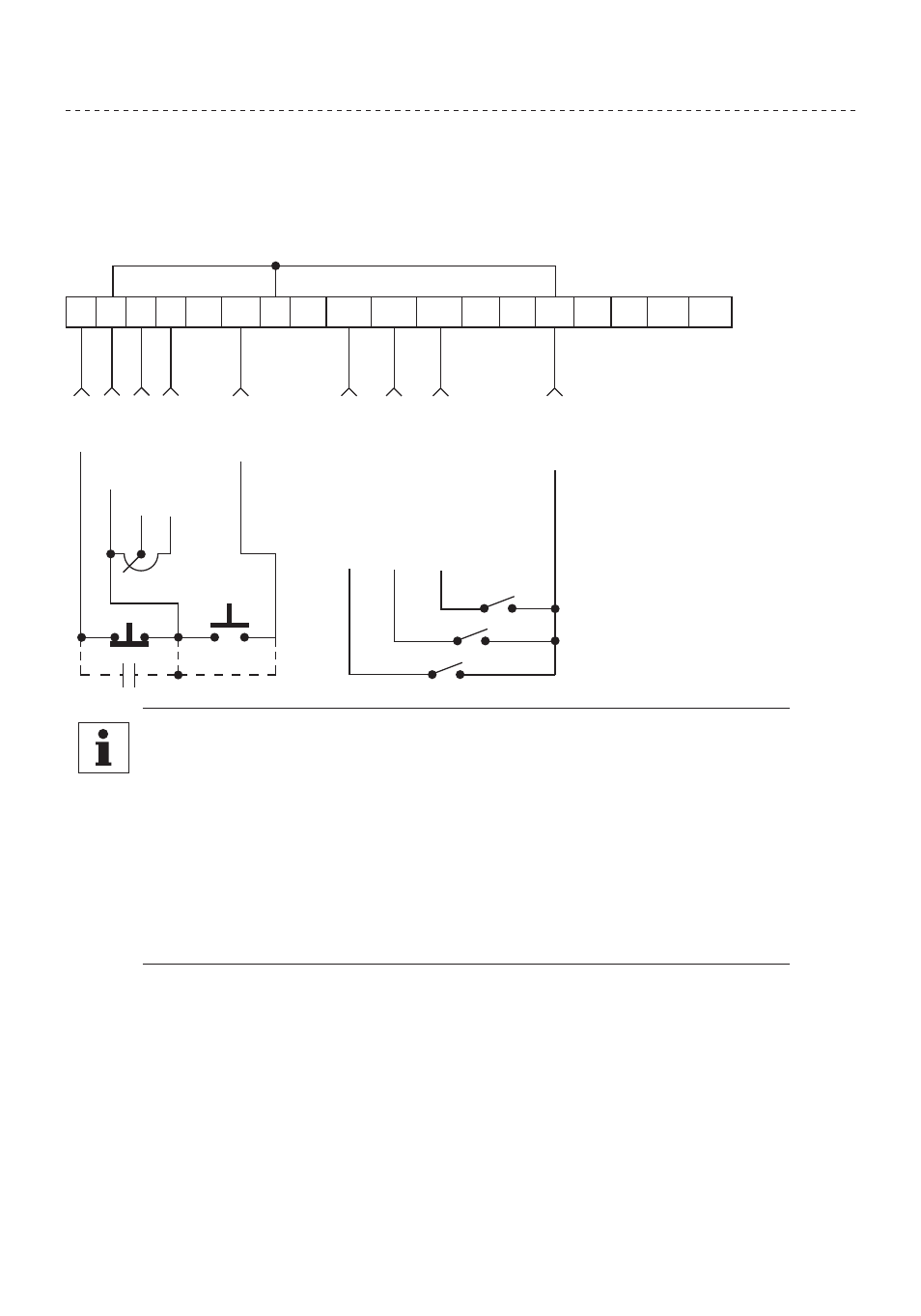
3.6.5 Speed Pot and Preset Speed Control
Shown below is the wiring for SPEED POT and/or PRESET SPEED control, and either a two-wire or
three-wire start/stop circuit:
1 2 5 6
12
TXA TXB
2
13A 13B 13C
14
15
2
STO
P
C
O
MM
ON
0-10 VDC
IN
PU
T
STA
RT
PR
ESET SPEED SELECT
C
O
MM
ON
11
25
31
30
10 VDC
SU
PPL
Y
2.5k - 10kΩ
PR
ESET SPEED SELECT
PR
ESET SPEED SELECT
The TB-2 terminals are internally connected to each other
NOTE
• Program the PRESET SPEEDS (Parameters 31-37) to the desired values.
• PRESET SPEED #2 (04), and TB-13C (Parameter 12) to PRESET SPEED #3 (04). To
select a preset speed, close the appropriate TB-13 terminal(s) to TB-2 (refer to
Parameters 31-37 for the Preset Speed Activation table).
• If reverse rotation is also required, TB-13A cannot be used as a PRESET SPEED
SELECT. TB-13A must be programmed to select RUN REVERSE (05) or START
REVERSE (06), leaving only TB-13B and TB-13C to select preset speeds.
• For speed pot control, program Parameter 05 - STANDARD SPEED SOURCE
for 0-10 VDC (03). If none of the preset speeds are selected (all of the TB-13
terminals are open), the drive will respond to the speed pot.