Installation 3, 6 scf control wiring diagrams – Lenze SCF frequency inverter User Manual
Page 23
Lenze 13466146 EDBSF01 v24 EN
23
Installation 3
3.6
SCF Control Wiring Diagrams
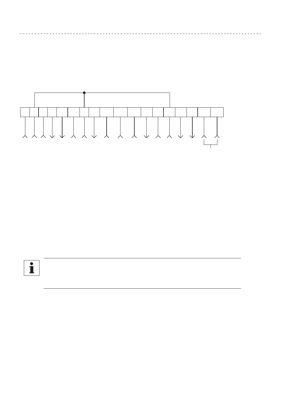
3.6.1 SCF Terminal Strip
Shown below is the terminal strip on the main control board, along with a brief description of the
function of each terminal.
1 2 5 6
12
TXA TXB
2
13A 13B 13C
14
15
2
STO
P
C
IR
CU
IT C
O
MM
ON
0-10
VDC SPEED R
EFER
ENC
E I
N
PU
T
10
VDC SU
PPL
Y FOR SPEED P
O
T
0-10 OR 2-10
VDC OU
TPU
T: FR
EQ
. OR L
O
AD
0-10 OR 2-10
VDC OU
TPU
T: L
O
AD
C
IR
CU
IT C
O
MM
ON
STA
RT
TB-13A F
U
NCT
ION SELECT
TB-13B F
U
NCT
ION SELECT
TB-13C F
U
NCT
ION SELECT
OPEN-C
OLLECT
OR OU
TPU
T
OPEN-C
OLLECT
OR OU
TPU
T
R
S-485 SER
IAL
C
O
MM
U
N
IC
AT
IONS
C
IR
CU
IT C
O
MM
ON
4-20 mA SPEED R
EFER
ENC
E I
N
PU
T
11
25
31
30
12
VDC SU
PPL
Y (50 mA M
AX)
The TB-2 terminals are internally connected to each other
NOTE
The function of terminals TB-13A, TB-13B, TB-13C, TB-14, TB-15, TB-30, and TB-31
are dependent on the programming of certain parameters. Refer to Section 4.4 -
Description of Parameters.
Additional information on operating the drive from the terminal strip can be found in Section 3.5. The
following diagrams provide a quick reference to wire the drive for the most common configurations.