4 wiring, 1 operation with ecsxe power supply module, Wiring – Lenze ECSCKxxx User Manual
Page 56: Operation with ecsxe power supply module, Electrical installation, Stop
Electrical installation
Wiring
Operation with ECSxE power supply module
l
56
EDKCSCK002 DE/EN/FR 1.1
4.4
Wiring
Install the capacitor module between the power supply module and the axis mo-
dule(s).
If the total cable length in the DC−bus connection is longer than 5 m, install the ca-
pacitor module as close as possible to the axis module with the highest power.
4.4.1
Operation with ECSxE power supply module
(
Stop!
ƒ
Permanently bridge the charging current limitation (X26) of the
capacitor module (X26 = HIGH).
ƒ
Only release the controller (X6/SI1 = HIGH) if the power supply
module ECSxE displays "Ready for operation" (X6/DO1 = HIGH).
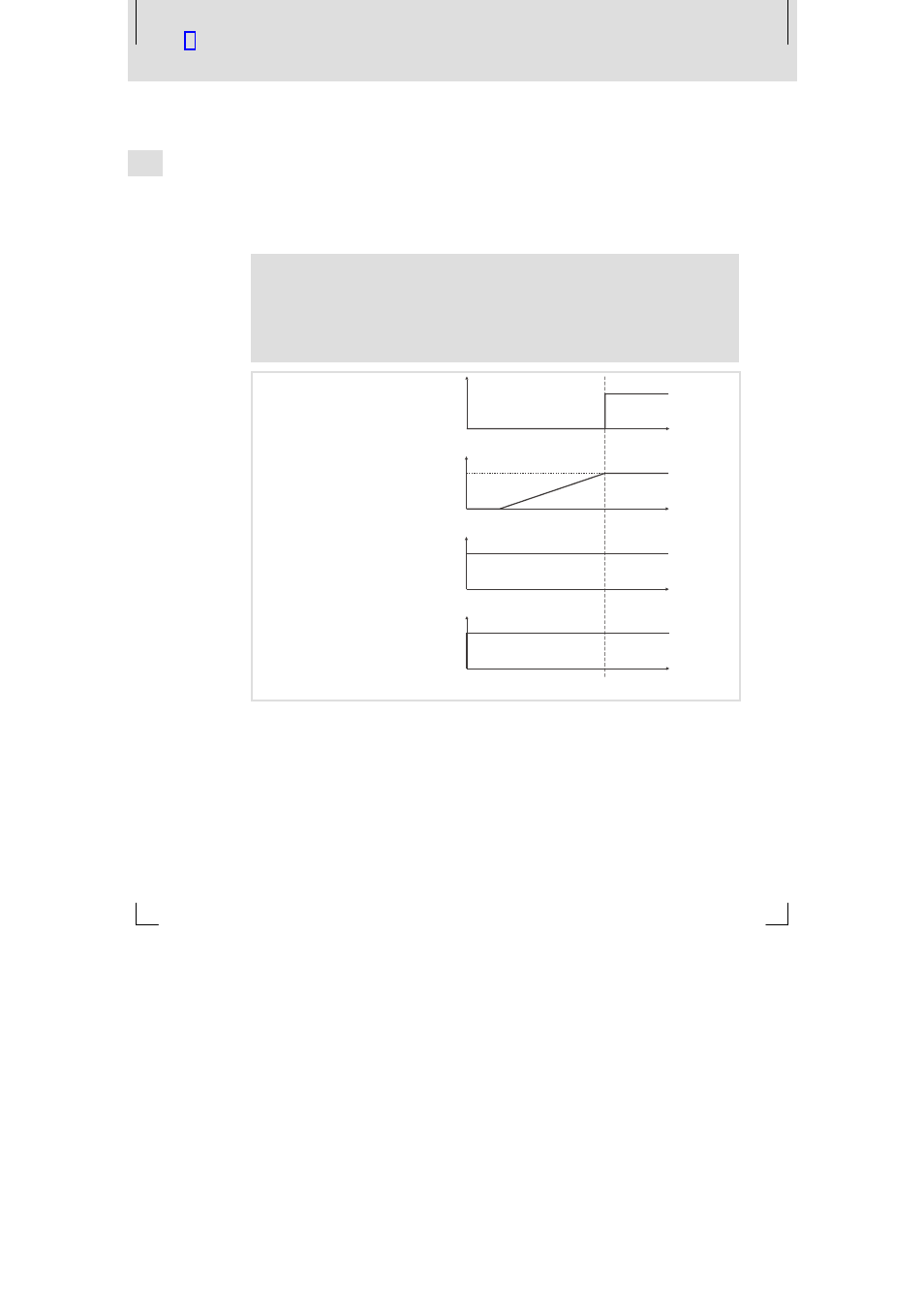
t [s]
HIGH (1)
LOW (0)
ECSx
: X6/SI1
ü
ECSxE: X6/DO1
t [s]
100 %
0 %
t [s]
HIGH (1)
LOW (0)
ECSxK: X26 (24 V DC)
ECSxE: X6/DI1
ECSxE: X6/DI2
t [s]
HIGH (1)
LOW (0)
K1
U
ZK
ECSXK010
Fig.9−1
Level/time diagrams for operation with ECSxE power supply module
ECSx
ü
Axis module of series ECS
ECSxE
Power supply module of series ECS
U
ZK
DC−bus voltage
ECSxK
Capacitor module of series ECS
K1
Mains contactor