10system variables and flags summary, System variables and flags summary, 10 system variables and flags summary – Lenze PMSS1000 Simple Servo User Manual
Page 31
Indexer-Programmer-Manual.pdf REV 1.3
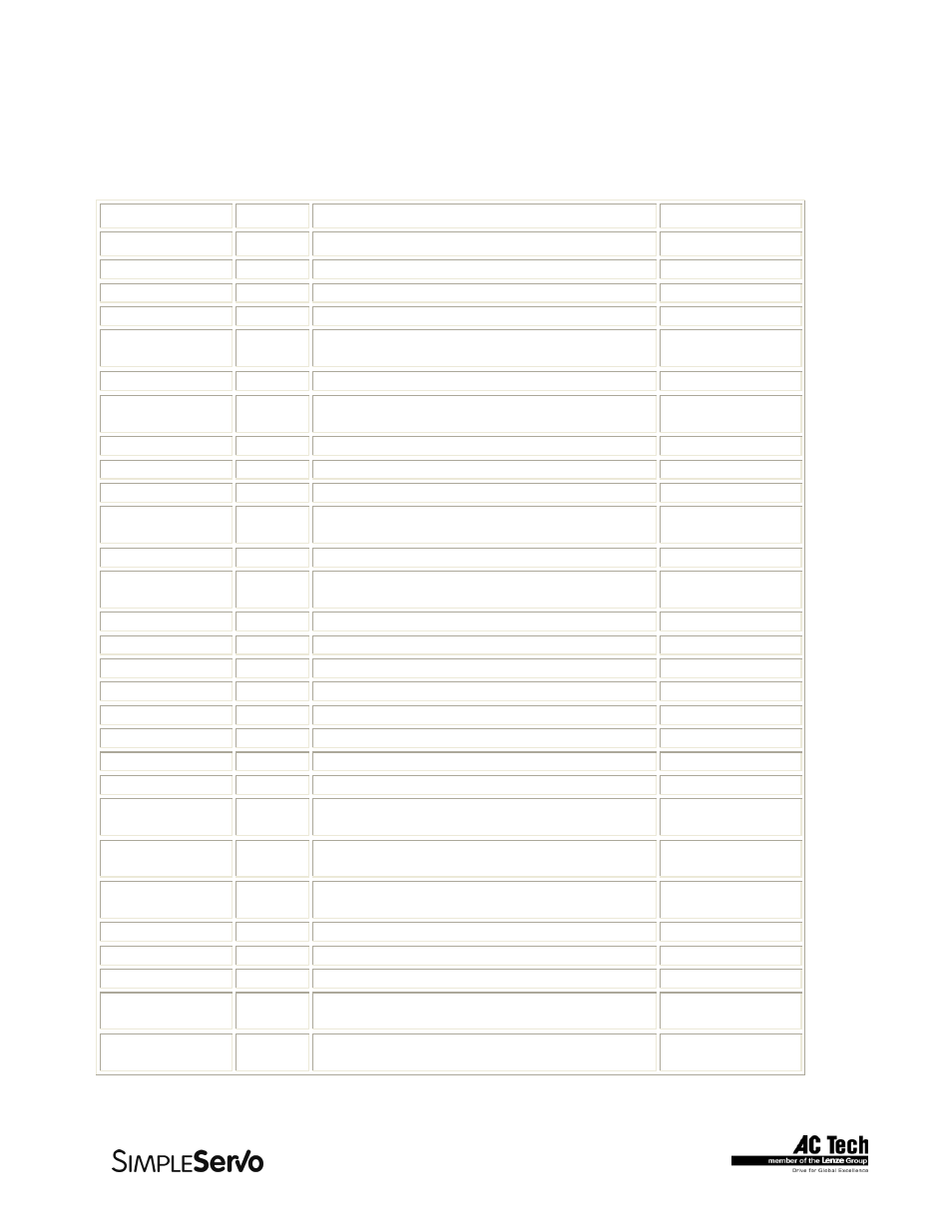
2.10 System Variables and Flags Summary
Below is the table of System Variables and Flags, sorted by type. Variables can be Read-Only (R) or
Read/Write (R/W) types. System Flags are always Read Only (R).
Variable Access
Variable
Description
Units
UNITS
R/W
User Units scale.**
NOTE 1
UserUnits/Rev
APOS
R/W
Actual motor position
User Units
TPOS
R
Theoretical/commanded position
User Units
TV
R
Commanded velocity in
User Units/Sec
RPOS
R
Registration position. Valid when system flag
F_REGISTARTION set
User Units
TA R
Commanded
acceleration
INPOSLIM R/W
Maximum allowable deviation of position for
INPOSITION Flag to remain to be set
User Units
MAXV
R/W
Maximum velocity for motion commands
User Units/Sec
ACCEL
R/W
Acceleration for motion commands
User Units/Sec
2
DECEL
R/W
Deceleration for motion commands
User Units/Sec
2
QDECEL
R/W
Quick Deceleration for STOP MOTION QUICK
statement
User Units/Sec
2
VEL
R/W
Set Velocity when in velocity mode
User Units/Sec
GRATIO
R/W
Gear Ratio between master encoder
and motor
-
MEPPR
R/W
Master Encoder resolution.
Pulses
PGAIN_P R/W
Position
loop
P-gain
-
PGAIN_I R/W
Position
loop
I-gain
-
PGAIN_D R/W
Position
loop
D-gain
-
PGAIN_VFF
R/W
Position loop VFF (velocity feed forward) gain
-
PGAIN_ILIM
R/W
Position loop I gain limit
-
VGAIN_P
R/W
Velocity loop P-gain
-
VGAIN_I
R/W
Velocity loop I-gain
-
INPUTS
R
Digital Inputs states. First 12 bits corresponds
to 12 SSi inputs
-
OUTPUTS
R/W
Digital outputs. First 5 bits represents outputs
From #0 to #4
-
INDEX
R/W
Lower 8 bits are used. See ASSIGN statement
for details.
-
PHCUR R
Motor
phase
current
A(mpere)
DSTATUS
R
Status flags register
-
DFAULTS
R
Fault code register
-
AIN R
Analog input. Scaled in volts.
Range form –10 to +10
V(olt)
AOUT
R/W
Analog output value in Volts.
Valid range from –10 to +10 (V)
NOTE 2
V(olt)
31