10motion, Motion, 10 motion – Lenze PMSS1000 Simple Servo User Manual
Page 21: Indexer-programmer-manual.pdf rev 1.3, Ssi position and velocity regulator's diagram
Indexer-Programmer-Manual.pdf REV 1.3
1.10 Motion
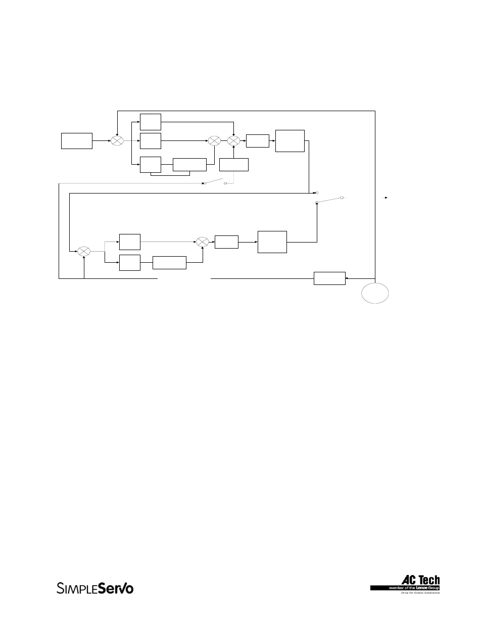
SSi position and velocity regulator's diagram
P term
I term
Kff term
I term Limit and
unti wind-up
Current
limiter
Velocity Command
Biquad
convergence
filter
I term
P term
I term Limit and
unti wind-up
Current
limiter
Biquad
covergence
filter
Scale factor
Primary
Encoder
Mechanical Velocity feedback
To Torque amplifier
PIVFF Mode
P+V Mode
P+V Mode
PIVFF Mode
Velocity
estimator
Position
Command
Position Feedback
"Position Command" in regulator's diagram is produced by trajectory generator. Trajectory generator
processes generated motion commands, produced by User's program motion statements, in order to
calculate position increment or decrement or also called "index" value for every servo loop. This way
target (or theoretical) position supplied to regulator input. The main job of the regulator is to control motor
shaft torque and velocity such way that actual position of the motor shaft, measured by processing
motor's encoder position feedback, matches target position as closed as possible. Of course there is
always will be the error in position following. Such error called "Position Error" and is expressed as:
Position Error = Target Position - Actual Position
When Position Error exceeds certain threshold value "Position Error Excess" fault #7 will be generated.
You can set allowable Position Error limit and Position Error Time (how long is a delay before fault
generated). These parameters can be set only using MotionView software.
Motion Modes
There is three modes SSi can operate in: Indexing (profiling) mode, Velocity mode and Gear mode.
Indexing is a default mode. All user program generated moves are executed in this mode. Velocity and
Gearing mode are covered in details in section 2.13.
21