Lenze PMSS1000 Simple Servo User Manual
Page 17
Indexer-Programmer-Manual.pdf REV 1.3
Limit switches input functions
Inputs A1 and A2 have secondary functions as Hard Limit Switch Negative and Hard Limit Switch Positive
respectively. From MotionVew's I/O folder you can select what type of action to perform when one of the
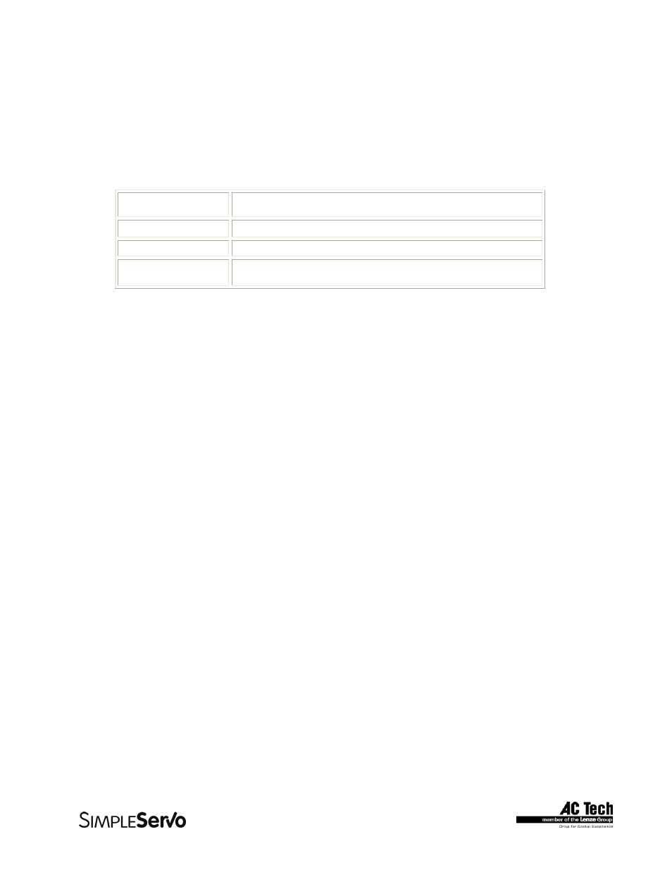
inputs is activated. Refer to the table below for list of possible actions.
Action Description
Not Assigned
No action. Input functioning as regular input
Fault
Input activation cause disable and fault
Stop and Fault
Input activation causes deceleration with rate set by
System Variable QDECEL and then disable and fault
Digital Outputs Control
There are total of 5 outputs. 4 are general purpose programmable and 1 dedicated.
Dedicated output turns ON when system status is READY and cannot be controlled from the program.
The rest of 4 outputs could be assigned special function through MotionView or executing Host Interface
commands. You can turn ON (set) or turn OFF (clear) particular output by writing to corresponding
System Flag or setting particular bit(s) in System Variable OUTPUT. Output can be control by program if
it is not assigned to one of the special functions. In this case, output is controlled internally and changing
its value from within program (or via Host Interface) has no effect on output. Table below summarizes
outputs functions and corresponding flags in DSTATUS System Variables. To set output write to its flag
any non 0 value (TRUE). To clear output write to its flag 0 (FALSE). You also can use flags in expression.
If expression evaluates to TRUE then output will be turned ON. It will be turned OFF otherwise.
Example:
;Following code sets and clears some outputs
;
OUT1 =1
;turn OUT1 ON
OUT2=10
;any value but 0 turns output ON
OUT3=0
;turn OUT3 OFF
OUT2 = APOS>3 && APOS<10
;ON when position within window
;OFF
otherwise
Function
Related Flag # from DSTATUS System Variable
Motion Complete
25
In Position Window
5
Fault 3
In Motion
Inverse of flag 25
Ready 0
17