5 terminal assignment, Wiring the installation backplane – Lenze E94AZPP User Manual
Page 54
Wiring the installation backplane
Wiring
Terminal assignment
l
54
EDK94ZPP0364 DE/EN/FR/ES/IT 2.1
5.3.5
Terminal assignment
I
Tip!
Complete the wiring of the installation backplane before plugging
in the standard device. The upper terminals of the installation
backplane cannot be connected with a plugged−in standard device.
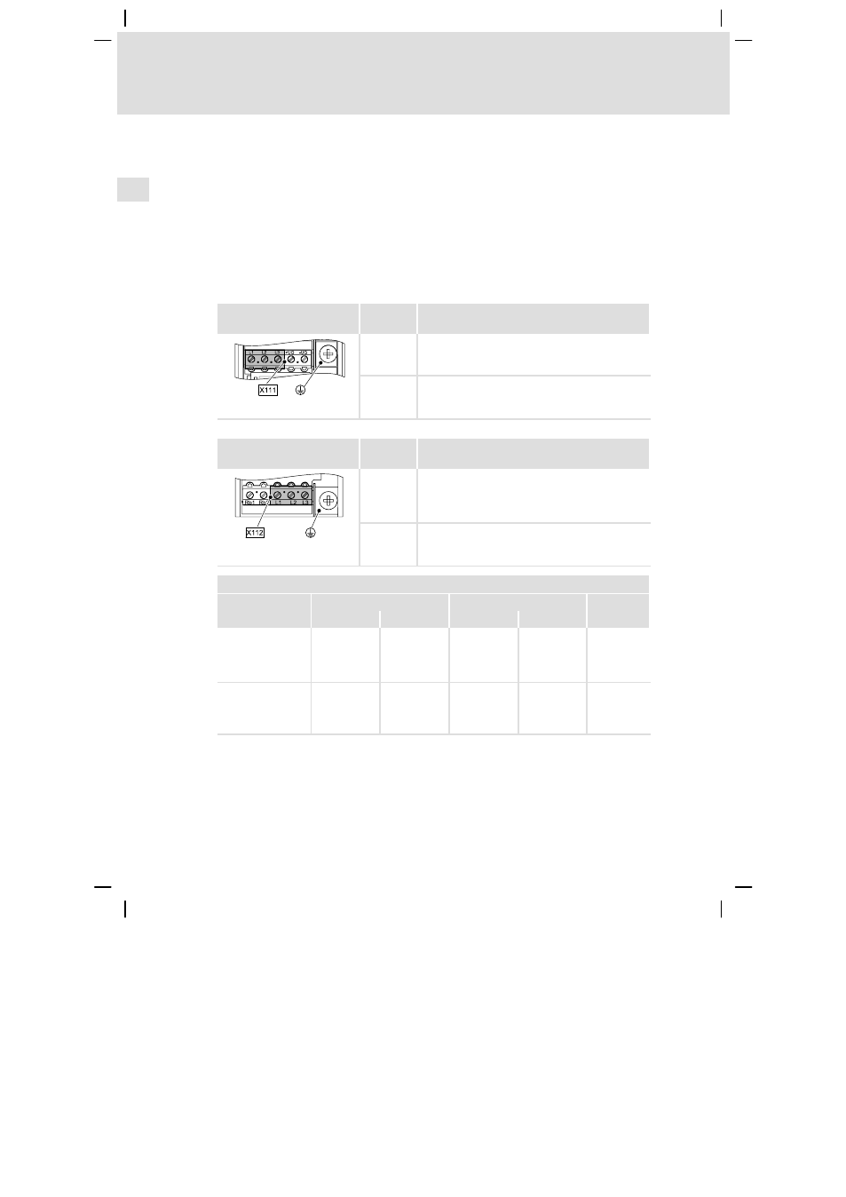
Mains
Terminal X111
(left part)
Labelling
Description
L1
L2
L3
Connection of the mains phases
E94APNE0xx4/E94AZxPxxx4: L1, L2, L3
E94ARNE0xx4/E94AZMR0xx4xDB: L1.1, L2.1, L3.1
+
Terminal for the supply−side PE conductor with M5
ring cable lug
SSP940X111
Terminal X112
(right part)
Labelling
Description
L1
L2
L3
Connection of the mains phases
E94APNE0xx4/E94AZxPxxx4:
alternatively at the bottom L1, L2, L3
E94ARNE0xx4/E94AZMR0xx4xDB: L1.2, L2.2, L3.2
+
Terminal for the supply−side PE conductor with M5
ring cable lug
SSP940X112
Terminal data
Max. conductor cross−section
Tightening torque
!
[mm
2
]
[AWG]
[Nm]
[lb−in]
Device sizes 1+2:
flexible
with wire end
ferrule
2.5
12
0.5 ... 0.6
4.5 ... 6.2
PZ0
Device size 3:
flexible
with wire end
ferrule
10
6
1.2 ... 1.5
10.6 ... 13.3
PH1