2 byte 1: service, Byte 1: service, 9parameter data transfer – Lenze E84AYCPM User Manual
Page 53
9
Parameter data transfer
9.2
DRIVECOM parameter data channel (DP-V0)
53
Lenze · E84AYCPM communication module (PROFIBUS®) · Communication Manual · DMS 5.0 EN · 11/2012 · TD17
_ _ _ _ _ _ _ _ _ _ _ _ _ _ _ _ _ _ _ _ _ _ _ _ _ _ _ _ _ _ _ _ _ _ _ _ _ _ _ _ _ _ _ _ _ _ _ _ _ _ _ _ _ _ _ _ _ _ _ _ _ _ _ _
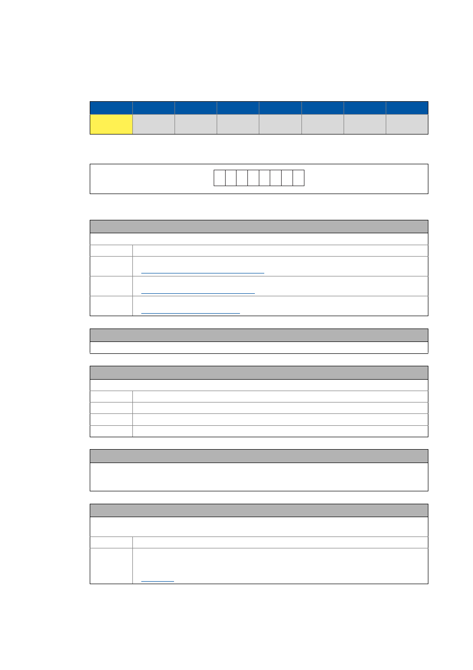
9.2.2
Byte 1: Service
Request and response control for the parameter data channel
[9-1]
Method of counting for bits 0 ... 7
Byte 1
Byte 2
Byte 3
Byte 4
Byte 5
Byte 6
Byte 7
Byte 8
Service
Subindex
Index
High byte
Index
Low byte
Data 4 /
Error 4
Data 3 /
Error 3
Data 2 /
Error 2
Data 1 /
Error 1
7
6
5
4
3
2
1
0
Bit 0 ... 2: Request
Read/write request from the master to the inverter
000 No request
001 Read request
Reading parameter data from the inverter ( 54)
010 Write request (write data to the inverter)
Writing parameter data to the inverter ( 54)
100 Data transfer abort by the master
Data transfer abort by the master ( 55)
Bit 3
Reserved
Bit 4/5: Data length
Data length ≤ 4 bytes in the telegram bytes 5 ... 8 (data 1 ... 4 / error 1 ... 4)
00 1 byte
01 2 bytes
10 3 bytes
11 4 bytes
Bit 6: Handshake
Indicates a new request.
• The state of this (toggle) bit is changed by the master for every new request.
• The inverter copies the bit into its response telegram.
Bit 7: Status
Status information from the inverter to the master when sending the request confirmation.
This status bit informs the master whether the request has been carried out without errors.
0 Request completed without errors.
1 Request not completed because of an error.
• The set status bit indicates that the telegram is an "error telegram". The data of bytes 5 ... 8 (data/
error) must be interpreted as an error message.