Assembly, Frame assembly, Chapter 2 – Landoll MCL/MCC/MCLS/MLCS/MCCS 1483, 1643, 1803 RIGID PULVI-MULCHER User Manual
Page 11: Caution frame assembly
2-1
Chapter 2
Assembly
CAUTION
Frame Assembly
1.
Place Front and Rear Frame Tubes on supports
spaced 10’ apart. Ensure supports are rated at
2,000lbs each.
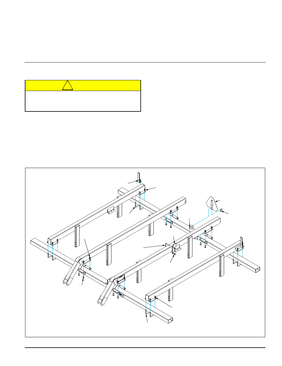
2.
Position Inner Frame Tubes. Fasten Inner Frame
Tubes to Front and Rear Tubes with 3/4”-10 X 2”
HHCS, Lock Washers and Nuts. Ensure that the
Inner Frame Tubes are square with the Front and
Rear Frame Tubes. See Figures 2-1 and 2-2.
3.
Position Outer Frame Tubes. Fasten with 5/8”-11
U-Bolts, Lock Washers and Nuts. See Figures 2-1
and 2-2.
4.
Install the Relief Valve Bracket. Fasten with 5/8”-11
U-Bolts, Lock Washers and Nuts.
5.
Install the SMV sign using two 5/16-18 HHCS,
Washers, and Lock Nuts.
6.
Tighten all hardware to the recommended torques.
See Page 4-1.
Figure 2-1: Frame Assembly
Do not work on or under this machine unless
securely
blocked and supported by a hoist or
tractor or by other sufficient means.
HHCS,
3/4-10 X 2
Hex Nut, 3/4-10
Lock Washer
U-Bolt, 5/8-11
Hex Nut 5/8-11
Lock Washer
SMV
and Bracket
HHCS, 5/16-18 X 1
Flat Washer
Lock Nut,
5/16-18
Relief Valve
Bracket
U-Bolt,
5/8-11
Hex Nut, 5/8-11
Lock Washer
Decal Bracket
U-Bolt,
5/8-11
Hex Nut 5/8-11
Lock Washer