Hydraulic schematic - vacuum fan motor system, Hydraulic schematic - vacuum fan motor system -31 – Kinze 3140 Stack Fold Planter Rev. 7/14 User Manual
Page 137
TM
Model 3140
M0245-01
9/12
6-31
Lubrication and Maintenance
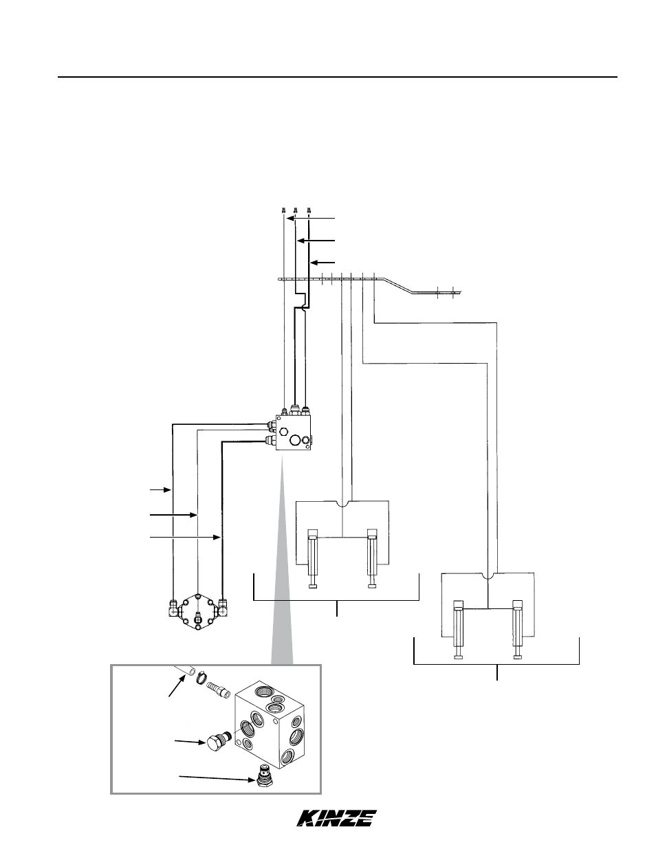
HYDRAULIC SCHEMATIC - VACUUM FAN MOTOR SYSTEM
Check Valve Assembly
(Located On R.H. Side
Of Fan Assembly)
Bulkhead Mount
Fan Motor
Assembly
See “HYDRAULIC SCHEMATIC -
FOLD SYSTEM”
See “HYDRAULIC SCHEMATIC -
ROW MARKER SYSTEM”
⅜
" Hose (Case Drain)
½
" Hose (Pressure)
¾
" Hose (Return)
½
" Hose
⅜
" Hose
¾
" Hose
Tractor Remote Valves
Vaccum Fan Motor Valve Block Assembly
(See Machine Operation Section)
Drain Hose
Relief Valve
Check Valve
NOTICE
Connect hydraulic motor case drain to a case drain return line with
zero pressure on tractor or hydraulic motor will be damaged. DO
NOT connect hydraulic motor case drain to SCV outlet. Contact
tractor manufacturer for specific details on “zero pressure return”.