310aa v – Bryant Series E/F 310AAV User Manual
Page 50
50
11
NO PREVIOUS CODE – Stored codes
are erased
after 72 hours
. On RED LED
boards stored status codes can also be
erased whene
v
e
r po
wer (115V or 24V
)
is interr
upted.
Run system through a
heating or cooling cycle to chec
k system.
12
BLO
W
ER ON AFTER PO
WER UP
–
(115V OR 24V) – Nor
mal operation.
Bl
o
w
er r
u
ns f
o
r 90 seconds
, if unit is
po
wered up during a call f
o
r heat (R-W
closed) or when (R-W opens) dur
ing
the
b
lo
w
er on-dela
y per
iod.
1
3
LIMIT CIRCUIT LOCK
OUT – Loc
kout
occurs if the limit, draft saf
e
guard, flam
e
rollout, or b
loc
ked v
e
nt s
w
itch*(if used) is
open longer than 3 minutes
. Control will
auto-reset after 3 hours
. See code 33.
1
4
IGNITION LOCK
OUT – System f
a
iled to
ignite
gas and pro
v
e f
lame
in 4 attempts
.
Control will auto-reset after 3 hours
.
See status code 34.
21
GAS HEA
TING LOCK
OUT –
T
u
rn
off
po
wer and w
a
it 5 minutes to retr
y.
Chec
k f
o
r:
-
S
tuc
k
closed gas v
alv
e
rela
y on control.
-
M
is
wire or shor
t to gas v
a
lv
e wire
.
2
2
ABNORMAL FLAME-PR
O
V
ING SIGNAL
Flame is pro
v
ed while gas v
a
lv
e is de-
energiz
e
d.
Inducer will r
u
n until f
a
ult is
cleared.
Chec
k f
o
r:
-
S
tuc
k
open or leaky gas v
a
lv
e
.
23
PRESSURE SWITCH DID NO
T OPEN
Chec
k f
o
r:
-
O
bstr
ucted pressure tube
.
-
P
ressure s
witch stuc
k closed.
2
4
SECOND
A
R
Y
V
O
LT
A
GE
FUSE
IS
OPEN
Chec
k f
o
r:
-
S
hor
t circuit in secondar
y
vo
ltage (24V)
wir
ing including ther
mostat leads
.
Disconnect
ther
m
ostat leads to isolate
shor
t circuit.
3
1
PRESSURE SWITCH DID NO
T CLOSE
OR REOPENED – If open longer than
5
minute
s
, inducer shuts off f
o
r 15 minute
s
bef
ore retr
y.
If opens dur
ing b
lo
w
er on-
dela
y
per
iod,
b
lo
w
er will come on
fo
r th
e
selected b
lo
w
er off-dela
y.
Chec
k
f
o
r:
-
P
roper v
e
nt sizing.
-
L
o
w
inducer v
oltage (115V).
-
L
o
w
inlet gas pressure (if LGPS used).
-
Inadequate comb
ustion air supply
.
-
D
isconnected or obstr
u
cted pressur
e
tubing.
-
D
ef
ectiv
e
inducer motor
.
-D
e
fectiv
e
pressure s
witch.
-
E
xcessiv
e
wind.
-
Restr
icted v
ent.
33
LIMIT CIRCUIT F
A
UL
T – Indicates the
limit, draft saf
eguard, flame rollout, or
b
loc
k
ed v
e
nt s
witch* (if used) is open.
Blo
w
er will r
un f
o
r 4 minutes
or until open
s
w
itch remak
e
s whiche
v
e
r is longer
. If
open longer than 3 minutes
, code
changes to loc
k
out #13.
If open less
than 3 min.
status code #33 continues
to flash until b
lo
w
er shuts off
. Flame
rollout s
w
itch and BVSS requires manual
reset.
Chec
k f
o
r:
-
D
ir
ty filter or restr
icted duct system.
-
Loose b
lo
w
er wheel.
-D
ef
ectiv
e
s
witch or connections
.
-
D
ef
ectiv
e
b
lo
w
er motor or capacitor
.
-
Inadequate comb
ustion air supply
(flame rollout s
witch open).
-
R
estr
icted v
ent.
-P
roper v
ent sizing.
-
E
xcessiv
e
wind.
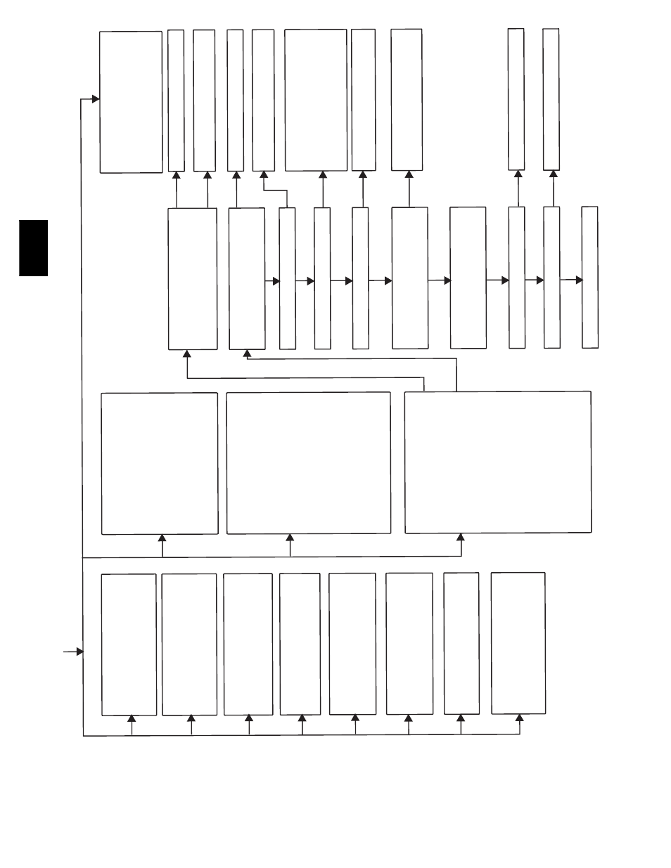
3
4
IGNITION PR
O
V
ING F
AILURE – If
flame
is not sensed dur
ing the tr
ial f
or ignition
per
iod,
the control will repeat the ignition
sequence 3 more times bef
ore loc
k
out
#14 occurs
. If flame signal is lost during
the b
lo
w
er on-dela
y per
iod, b
lo
w
er will
come on f
or the selected b
lo
w
er off-dela
y.
Chec
k
the f
ollo
w
ing items first bef
ore
proceeding to the ne
xt step
.
-
G
as v
alv
e tur
ned off
.
-
M
anual shut-off v
a
lv
e
.
-G
reen/Y
e
llo
w
wire MUST be connected
to fur
nace sheet metal
.
-
F
lame sensor must not be grounded.
T
o
deter
m
ine whether the prob
lem is in
the gas
v
a
lv
e
, igniter
, or flame sensor the
system can be operated
in
the component
test mode to chec
k the igniter
. First
remo
ve
the R ther
mostat connection from
the control and initiate the component
test sequence
. Does the igniter glo
w
orange/white
b
y
the end of
the 15 second
wa
rm
-up per
iod?
Unplug igniter har
n
ess from control and initiate
another component test sequence
. Chec
k
fo
r 115V between
pin 1 and NEUTRAL-L2 on
the control.
W
a
s 115V present f
or the 15
second per
iod?
Reconnect the R ther
mostat lead and set
ther
mostat to call f
or heat.
Connect v
oltmeter
across gas v
a
lv
e connections
. Does gas v
a
lv
e
receiv
e 24V?
Does gas v
a
lv
e open and allo
w
gas to flo
w
?
Do the main b
u
rn
ers ignite?
Do the main b
u
rn
ers sta
y
on?
Repeat call f
o
r heat and chec
k flame sensor
current dur
ing tr
ial f
o
r ignition per
iod.
Is the
DC microamps belo
w 0.5?
Is current near typical v
a
lue?
Will main b
u
rn
ers ignite and sta
y
on?
Fix
e
d.
Clean flame sensor with fine steel wool and
rechec
k current.
Nominal current is 4.0 to 6.0
microamps
.
45
CONTR
O
L CIRCUITR
Y
LOCK
OUT
A
u
to-reset after 1 hour loc
k
out due to:
-
Flame circuit f
a
ilure
.
-
G
as v
a
lv
e rela
y stuc
k open.
-
S
oftw
are chec
k error
.
Reset po
wer to clear lo
c
k
out.
Replace
control if code repeats
.
Replace fur
n
ace control.
Chec
k f
or continuity
in the har
ness and igniter
.
Replace def
e
ctiv
e component.
Chec
k connections
. If OK, replace control.
Chec
k that all gas v
a
lv
es are tur
n
ed on.
Replace v
a
lv
e
.
Chec
k f
o
r:
-
Inadequate flame carr
y
o
v
er or rough
ignition.
-L
o
w
inlet gas pressure
.
-
P
roper fir
ing rate
.
-
B
loc
k
ed or incorrect carr
y- o
v
e
r gap
.
(.045”
nominal)
Allo
w b
lo
w
er to come on and repeat test to
chec
k f
or inter
m
ittent operation.
Chec
k connections and retr
y.
If current is
near typical v
a
lue (4.0-6.0 nominal) and
b
u
rn
ers will not sta
y
on, replace control.
Replace electrode
.
Replace fur
n
ace control.
* Bloc
k
e
d v
ent s
witch used in Chimne
y Adapter Kit
YES
YES
YES
YES
NO
YES
YES
YES
NO
YES
NO
NO
NO
YES
NO
NO
NO
NO
310AA
V