JUMO 707020 dTRANS T02 - Four-Wire Transmitter Data Sheet User Manual
Page 7
2014-08-08/00379095
Data Sheet 707020
JUMO GmbH & Co. KG • 36035 Fulda, Germany
Page 7/12
Customized linearization
Electrical data
Version 707025/... (Ex)
Interpolation: linear
max. 41 calibration points
Interpolation: square-law
max. 53 calibration points
Interpolation: cube-law
max. 61 calibration points
Input of calibration points
through setup program (accessory)
Supply voltage
- types 707021/... and 707022/...
20 — 53V AC/DC, 48 — 63Hz or
110 — 240V AC +10/-15%, 48 — 63Hz
- type 707025/...
230V AC ±10%, 48 — 63Hz or
20 — 53V AC/DC, 48 — 63Hz
Power consumption
max. 5VA
Test voltage
to DIN 61010, Part 1
- between input or output and
supply
- with AC supply
- with AC/DC supply
2.3kV/50Hz, 1min
510V/50Hz, 1min
- between input and output
510V/50Hz, 1min
Isolation
- between input and output
- between input and mains supply
- between output and mains supply
- between output and setup plug
50V
250V
250V
no isolation between output and setup plug
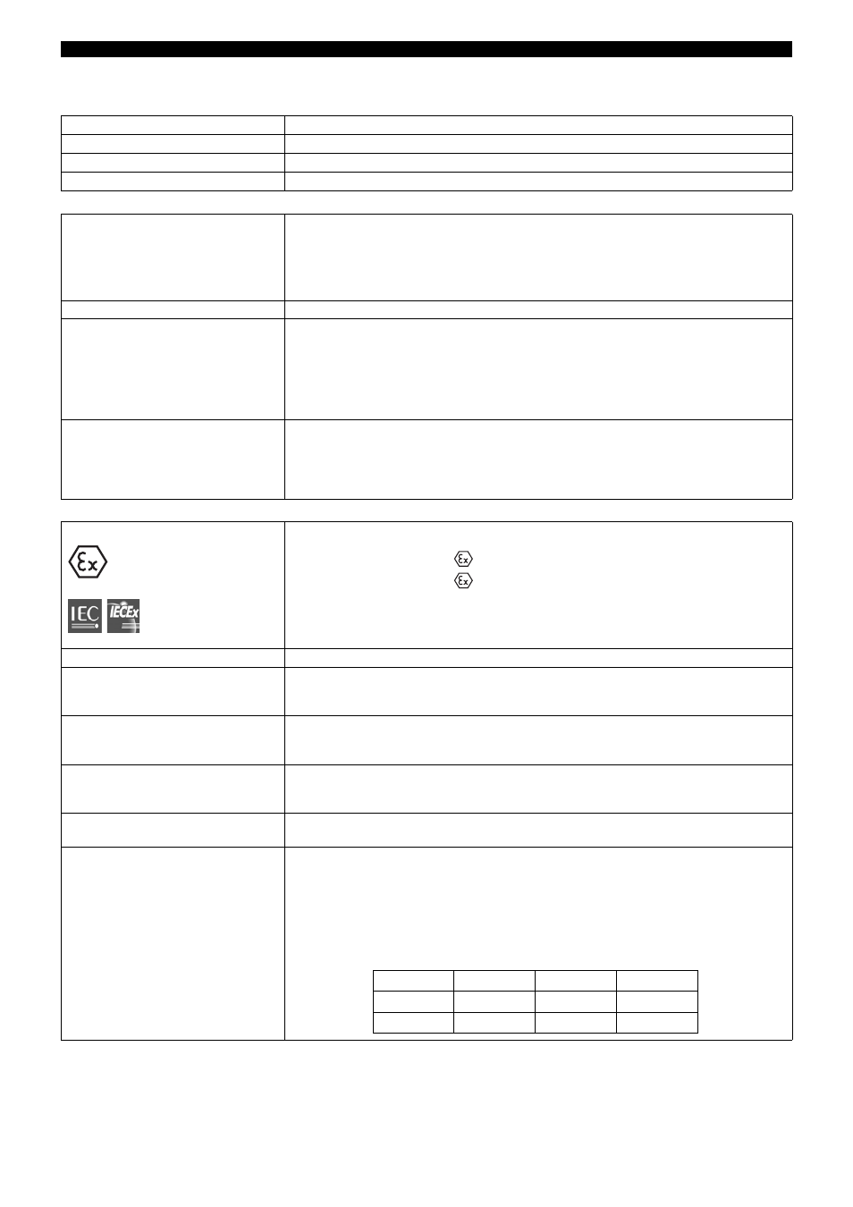
Marking
Ambient temperature range
-10 to +60°C
Supply circuit
(terminals L1(L+), N(L-) and PE)
Max. safe voltage
230V AC ±10%, 48 — 63Hz or
20 — 53V AC/DC, 48 — 63Hz
U
m
= 253V
Output circuit
(terminals 9(+) and 10(-))
Max. safe voltage
0 — 20mA
U
m
= 253V
Output circuit
(terminals 11(-) and 12(+))
Max. safe voltage
0 — 10V
U
m
= 253V
Setup circuit
Max. safe voltage
5V TTL level
U
m
= 253V
Sensor circuit
(terminals 1 through 5)
type of protection Intrinsic Safety
Ex ia IIC or Ex ia IIIC
Maximum values:
U
0
= 6.0V
I
0
= 18.9mA
P
0
= 28.4mW
linear characteristic
L
i
negligibly low
C
i
negligibly low
For relationship between explosion
group and the external reactances
reference is made to the table:
II (1) G [Ex ia Ga] IIC
II (1) D [Ex ia Da] IIIC
[Ex ia Da] IIIC
[Ex ia Ga] IIC
IIC
IIB
IIA
L
o
20 mH
20 mH
20 mH
C
o
1.3 µF
7.1 µF
10 µF