Connection diagram, Module slot 3 (top) fitted with one relay card – JUMO 706581 LOGOSCREEN nt Data Sheet User Manual
Page 12
2009-12-11/00504652
Data Sheet 70.6581
JUMO GmbH & Co. KG • 36035 Fulda, Germany
Page 12/18
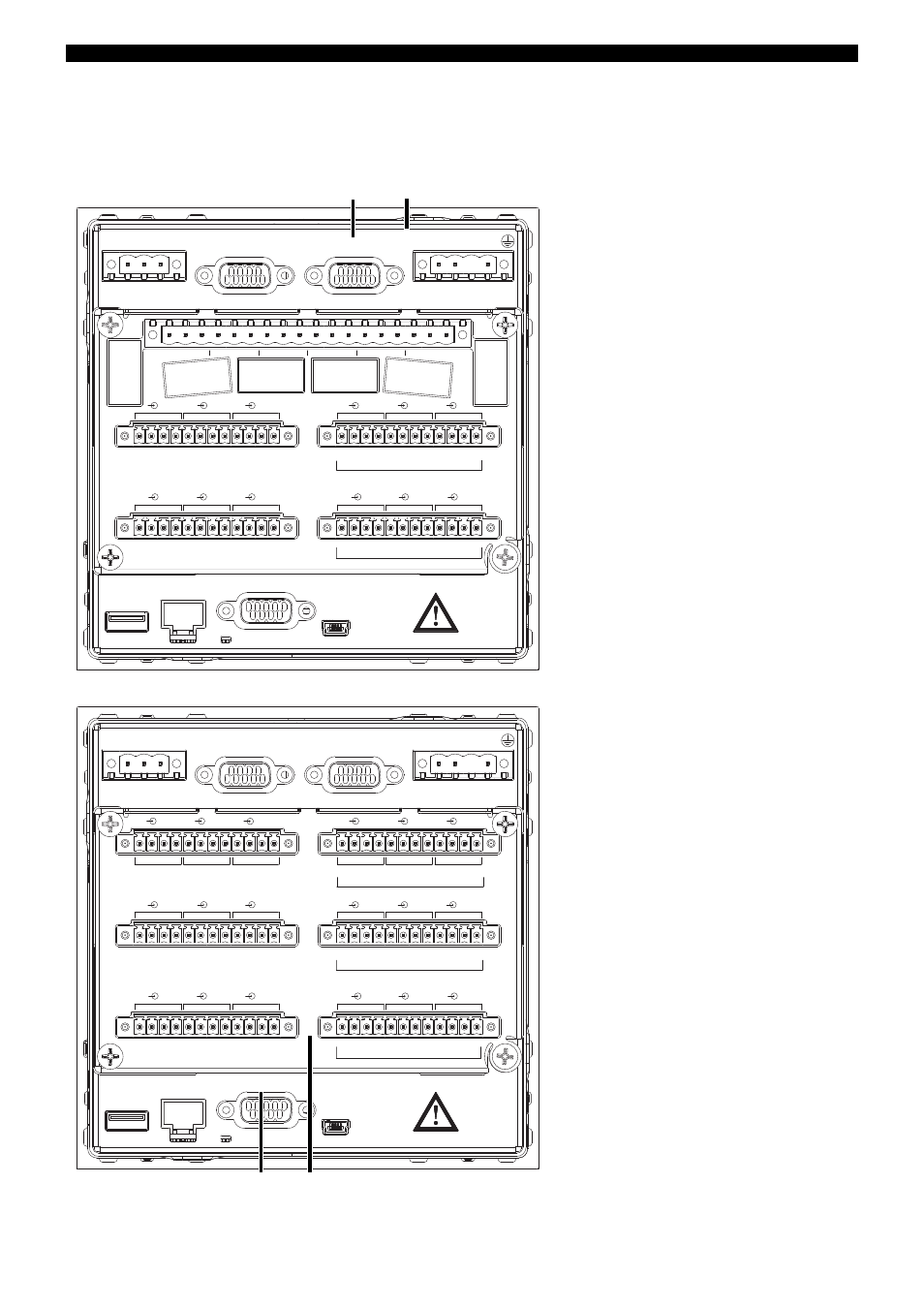
Connection diagram
Rear view with pluggable screw terminals
Instrument variant 1
Instrument variant 2
21
22
23
31
32
33
41
42
43
51
52
53
61
62
63
71
72
73
1
2
3
4
10
11
12
1
2
3
4
5
6
9
8
7
B12
B9
B10
B1
1
B13
B14
B15
B16
B4
B1
B2
B3
B5
B6
B7
B8
+
+
+
U
U
+ -
-
-
-
in
out
U
U
out
U
U
in
3
3
4
4
1
1
2
2
1
2
3
4
1
2
3
4
1
2
3
4
1
2
3
4
1
2
3
4
1
2
3
4
1
2
3
4
1
2
3
4
1
2
3
4
8.
9.
11.
10.
14.
3.
2.
1.
12 13
11
5.
6.
7.
PE
N
L1
(L+) (L-)
4.
15.
Module slot 3 (top)
fitted with one relay card.
}
Module slot 2 (middle)
fitted with 6 analog channels or
3 analog channels and
8 binary inputs/outputs.
}
Module slot 1 (bottom)
fitted with 6 analog channels or
3 analog channels and
8 binary inputs/outputs.
}
Connector number
13
14
15
16
17
18
4
3
2
1
B20
B17
B18
B19
B21
B22
B23
B24
B12
B9
B10
B1
1
B13
B14
B15
B16
B4
B1
B2
B3
B5
B6
B7
B8
+
+
U
U
U
+
+
U
U
+
+
U
-
-
-
-
-
-
in
out
in
out
in
out
1
2
3
4
1
2
3
4
1
2
3
4
9
8
7
1
2
3
4
10
11
1
2
3
4
1
2
3
4
12
1
2
3
4
1
2
3
4
1
2
1
2
3
4
3
1
2
3
4
1
2
3
4
1
5
4
2
3
4
6
1
1
2
2
3
3
4
4
1
2
3
4
1
1
2
2
3
3
4
4
12.
13.
11.
9.
8.
10.
3.
2.
1.
12 13
11
5.
6.
7.
PE
N
L1
(L+) (L-)
4.
15.
Module slot 3 (top)
fitted with 6 analog channels or
3 analog channels and
8 binary inputs/outputs.
}
Module slot 2 (middle)
fitted with 6 analog channels or
3 analog channels and
8 binary inputs/outputs.
}
Module slot 1 (bottom)
fitted with 6 analog channels or
3 analog channels and
8 binary inputs/outputs.
}
Connector number