6 technical data, 1 voltage supply, 2 control – JUMO 709050 IPC IGBT Power Converter IPC 70A Operating Manual User Manual
Page 39: 3 fault signal output, 4 general characteristics, Technical data, Voltage supply, Control, Fault signal output, General characteristics
02.08 [IGBT Power Converter 70A]
39
6 Technical data
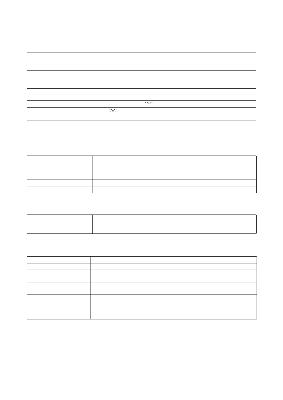
6.1 Voltage supply
6.2 Control
6.3 Fault signal output
6.4 General characteristics
Voltage supply
Power section
115V AC +15%/-20% 48 ... 63Hz
230V AC +15%/-20% 48 … 63Hz
400V AC +15%/-20% 48 … 63Hz
Voltage supply
Control section
115V AC +15%/-20% 48 ... 63Hz, 50VA (only with 115V AC in the power
section)
230V AC +15%/-20% 48 … 63Hz, 50 VA
Power consumption, control
section
approx. 50 VA
Load voltage U
L rms
20 V DC, 60 V, 90V, 120 V
Load current U
L rms
70A DC
Load type
Resistive loads
Effect on the supply
network
Additional interference suppression measures allow to meet limit valuesas per
EN 61 326.
Control signal
0 (4) … 20mA
R
i
= 50
Ω
0 (2) … 10V
R
i
= 25k
Ω
0 (1) … 5V
R
i
= 12k
Ω
Manual control through an external 5 k
Ω potentiometer
Input signal attenuation
Adjustment range 100 to 20%
Base load setting
0 ... 100 %
Relay (changeover contact)
without contact suppression
150000 switching actions at a contact rating of 3A/230V 50Hz (resistive
load)
Optocoupler output
I
Cmax
= 2mA, U
CEOmax
= 32V
Circuit variants
Single-phase operation
Operating modes
Amplitude control
Subordinate
control
As standard: free choice between U
2
-, P-, I
2
control via internal switches
Current limiting
In operation, the load current can be set in the range of 10 … 100% I
N
by a
trimmer on the front panel. This limits the rms-value of the load current.
Partial load failure
20 ... 100% of nominal current
Power level output
As standard: free choice between U
2
-, P-, or I
2
signal via internal switches,
adjustable 0 … 5V to 0 … 10V , I
max
≈ 2mA,
offset deviation:
≤ ± 5%